
Analytical Instrumentation for Critical Industrial Measurements
Blue Dragon Technology
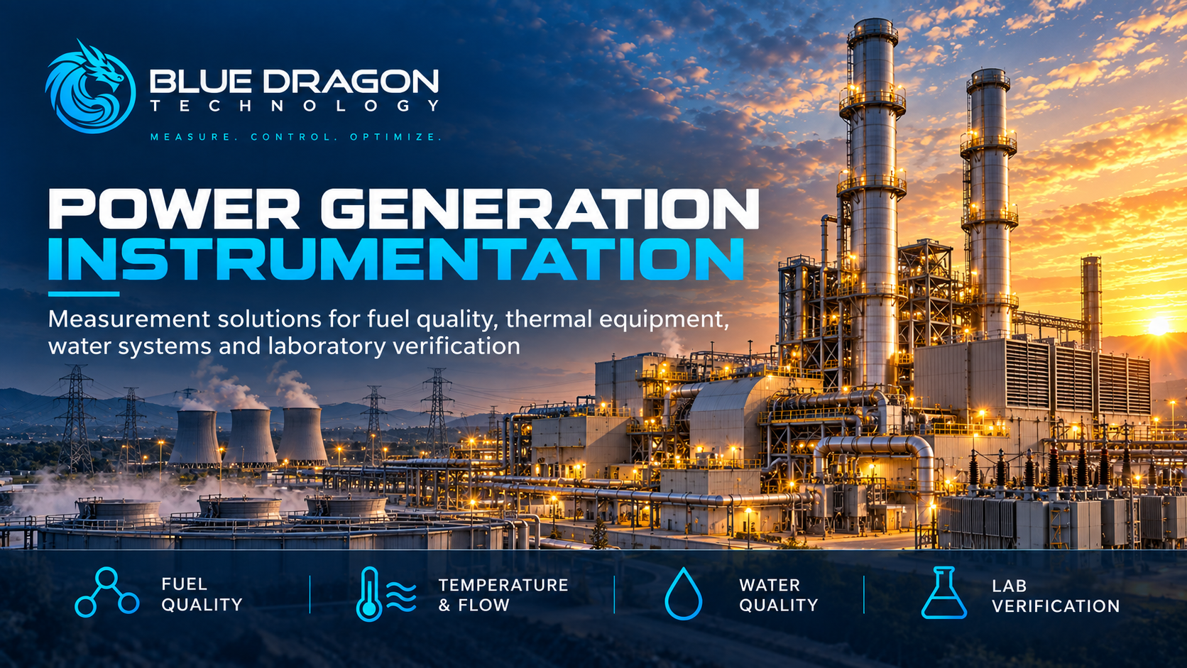
Power station at sunset with Blue Dragon branding and measurement themes covering fuel quality, temperature, flow, water quality and laboratory verification.

Power Generation Instrumentation: Measurement Solutions from Fuel Supply to Steam, Cooling Water and Wastewater

A turbine is often the most visible piece of equipment in a power plant, but power generation depends on more than the turbine. Fuel supply, combustion, heat recovery, steam generation, cooling water and wastewater treatment each introduce measurement requirements that influence operating and maintenance decisions.

Fuel-gas moisture, sulfur where relevant, gas-flow behavior, localized tube temperatures and water contamination can require different instruments at different process points. A useful measurement strategy connects those points to the questions that plant personnel need to answer.

Effective power generation instrumentation therefore combines fuel-quality analysis, ultrasonic gas-flow measurement, engineered temperature assemblies and water-quality instruments. Online monitoring, portable field verification and laboratory testing each contribute a different type of information.

The central principle is simple: select the measurement around the actual application and the decision it must support. Stream composition, sample phase, pressure, temperature, installation geometry, materials, maintenance access and the required reporting basis all influence the correct configuration.

This article uses thermal and combined-cycle generation as its main context, with relevant boiler, cogeneration and qualified liquid-fuel applications. It follows the measurement chain from incoming fuel through combustion and heat recovery to the steam-water cycle, cooling systems and wastewater.

Power Generation Measurement Solutions: Video Overview

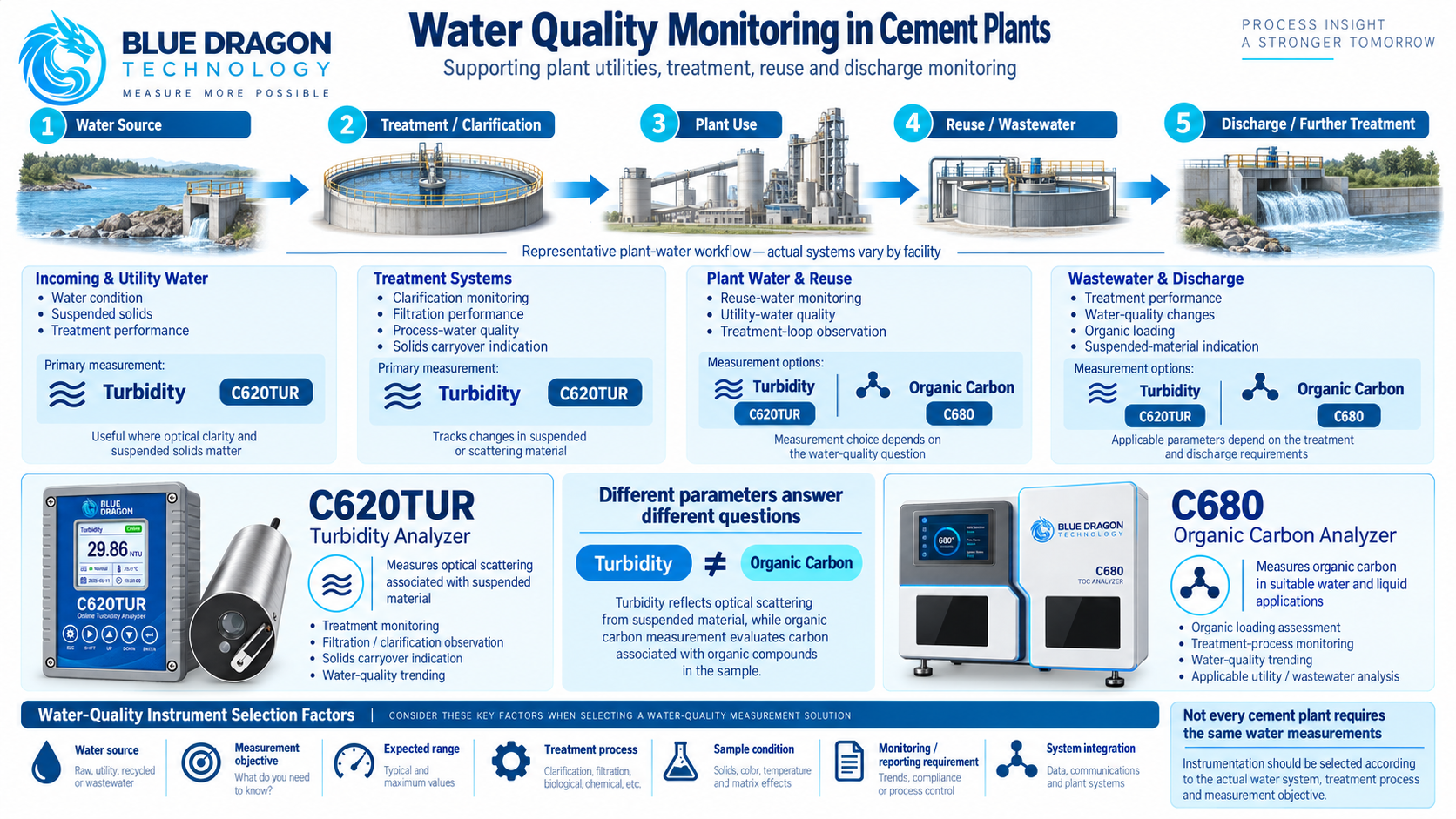
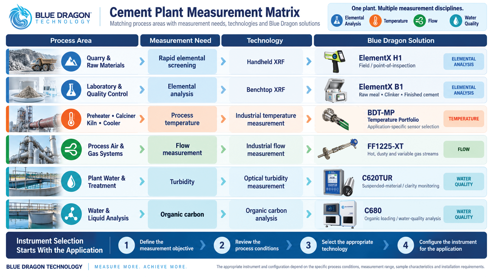
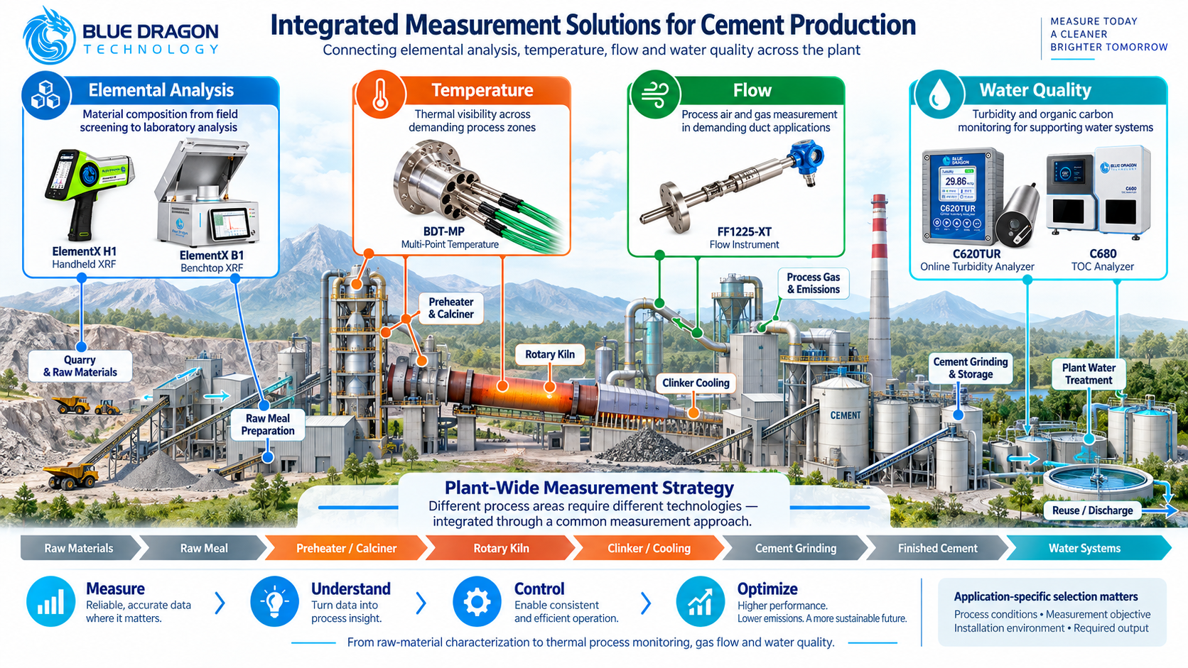
The Blue Dragon Technology presentation below provides a visual overview of measurement applications across fuel quality, gas flow, combustion exhaust, boiler and HRSG temperatures, water and steam-cycle chemistry, cooling water and wastewater. It also shows how the featured instruments can be grouped around practical plant requirements.

The sections below expand on the presentation, explaining the measurement principles, application conditions and verification arrangements that turn individual instruments into useful plant information.

Understanding the Power Plant Measurement Chain

A power plant contains several connected measurement environments. The fuel system establishes what is delivered to the combustion equipment. The thermal system converts fuel energy into useful work and, where applicable, recovers exhaust heat. Water and steam systems carry energy through the cycle, while cooling and wastewater systems support the wider operation.

In a combined-cycle plant, the gas turbine produces power and its exhaust transfers heat to a heat-recovery steam generator, or HRSG. Steam from the HRSG drives the steam turbine. Exhaust gas and steam follow separate paths, connected through heat transfer within the HRSG.

After expansion through the steam turbine, steam is condensed and the water returns through the condensate and feedwater systems. Makeup water replaces losses. Where a water-cooled condenser is used, the cooling-water circuit exchanges heat with the steam-water cycle while remaining a separate water system.

A boiler-based or cogeneration facility has a different arrangement, but the same measurement questions recur:

  • Fuel condition: Is the incoming fuel suitable for the equipment and operating requirement?
  • Gas quantity: How much fuel or process gas is moving through the defined measurement point?
  • Thermal condition: Where do local wall, equipment-surface or internal temperatures vary?
  • Water condition: What changes are occurring in treatment, high-purity water, cooling water or wastewater?

Mapping those questions to the plant layout helps establish measurement priorities before model selection. It also separates continuous operating trends from portable investigations and laboratory verification.
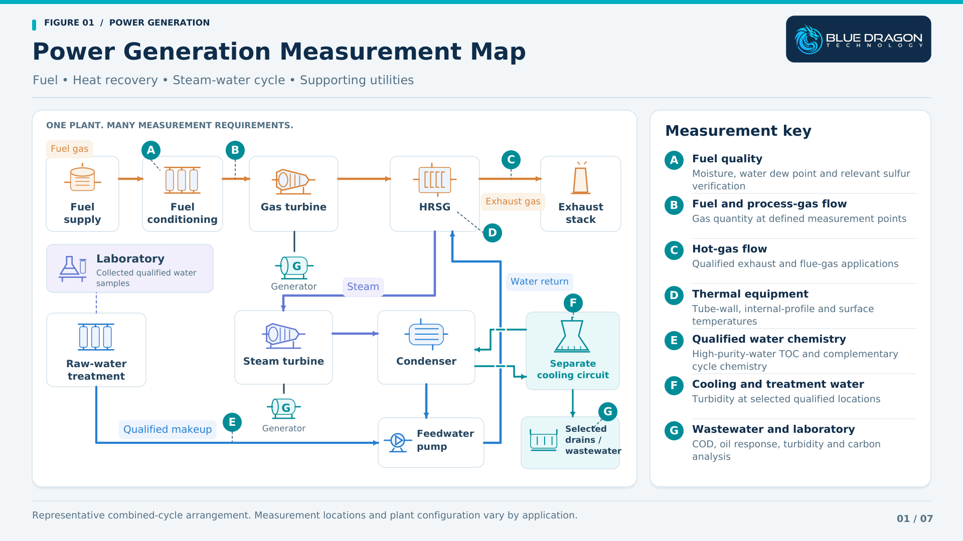
Combined-cycle plant map locating fuel, hot-gas, temperature, water-chemistry, cooling-water and wastewater measurements.

Figure 1. Representative combined-cycle power plant showing measurement areas across fuel delivery, heat recovery, the steam-water cycle and supporting utilities. The cooling circuit remains separate from the condensate and feedwater circuit.

Fuel Quality Before Combustion

Fuel quality begins with a clear analytical objective. Moisture, selective hydrogen sulfide and total sulfur describe different properties, and their relevance depends on the fuel, supply specification and receiving equipment. The sample phase and expected composition determine how the measurement should be made.

Fuel-Gas Moisture and Water Dew Point

Moisture measurement can help plant teams understand gas dryness, observe changes in conditioning and assess water-condensation risk at defined operating conditions. Water dew point is the temperature at which water condensation begins at the stated pressure; moisture concentration expresses the amount of water on a specified concentration basis.

Blue Dragon provides the FAS-SW Trace Moisture & Dew Point Transmitter and the FAS-W Online Moisture & Dew Point Analyzer for qualified gas applications. FAS-SW provides a compact continuous measurement arrangement, while FAS-W uses an automatic chilled-mirror approach with versions for water dew point, moisture concentration or both.

The application review should establish the gas composition, measurement pressure, expected range and sample-conditioning arrangement. Pressure reduction, cooling, liquid carryover, aerosols, sample-line materials and ambient moisture can affect how representative the delivered sample remains.

The required output should also be explicit. A dew-point result at one pressure and a moisture concentration at reference conditions answer related but different questions. Water-dew-point measurement should be distinguished from hydrocarbon-condensation measurement when defining the fuel-quality scope.

Portable Hydrogen Sulfide Verification

The Model 810H2S-P Portable Hydrogen Sulfide Tape Analyzer supports field verification, commissioning, temporary monitoring and troubleshooting in qualified gas applications. A pressure-fed sample is measured using the tape-based H₂S detection system.

Portable verification can help investigate an unexpected gas-quality result or compare conditions at selected sampling points. The sample composition, concentration range, transport arrangement and operating procedure should be defined before deployment. The portable model is intended for general-purpose, non-hazardous locations; a permanent online installation is a separate scope requiring its own review.

Total Sulfur in Qualified Liquid Fuels

The Model 800TS Online Total Sulfur Analyzer addresses total sulfur using catalytic conversion and ultraviolet fluorescence detection. Its documented standard liquid configuration is oriented toward suitable light-hydrocarbon samples, including diesel and related petroleum fractions.

Where a plant uses a qualified liquid fuel, sulfur analysis can support fuel-quality verification and investigation of changes between supplies. The proposed fuel, range, sampling arrangement and sample handling must be reviewed together. Heavy or otherwise different fuels require specific confirmation of the complete analytical configuration.

Application note: Water dew point, moisture concentration, selective H₂S and total sulfur are separate measurements. Define the property, sample phase, reporting basis and operating objective before selecting the instrument.

Fuel and Process-Gas Flow Measurement

Gas-flow measurement adds quantity information to the fuel-quality picture. A plant may need to follow fuel consumption, compare operating periods, observe flow changes during load transitions or investigate an auxiliary gas service. The measurement point and reporting basis determine how the result can be used.

The FF1225-A Single-Path Inline Ultrasonic Gas Flow Meter is a representative option for qualified fuel and industrial process-gas duties. Ultrasonic transit-time measurement relates the difference in acoustic travel times to gas velocity through the defined measuring geometry.

The final configuration depends on pipe dimensions, gas properties, pressure, temperature, normal and minimum flow, available straight runs and installation access. Flow disturbance, liquid carryover and contamination should be considered when selecting the meter location and evaluating the required performance.

The plant should establish whether it needs actual volumetric flow, flow at defined reference conditions or another specified output. Pressure, temperature and gas-property information may be required by the selected compensation and reporting arrangement.

Fuel-energy calculations require an appropriate heating-value basis as well as a compatible quantity measurement. Useful performance comparisons also require consistent time periods, operating conditions and data quality. Defining these relationships early helps the plant integrate the meter into the intended engineering workflow.
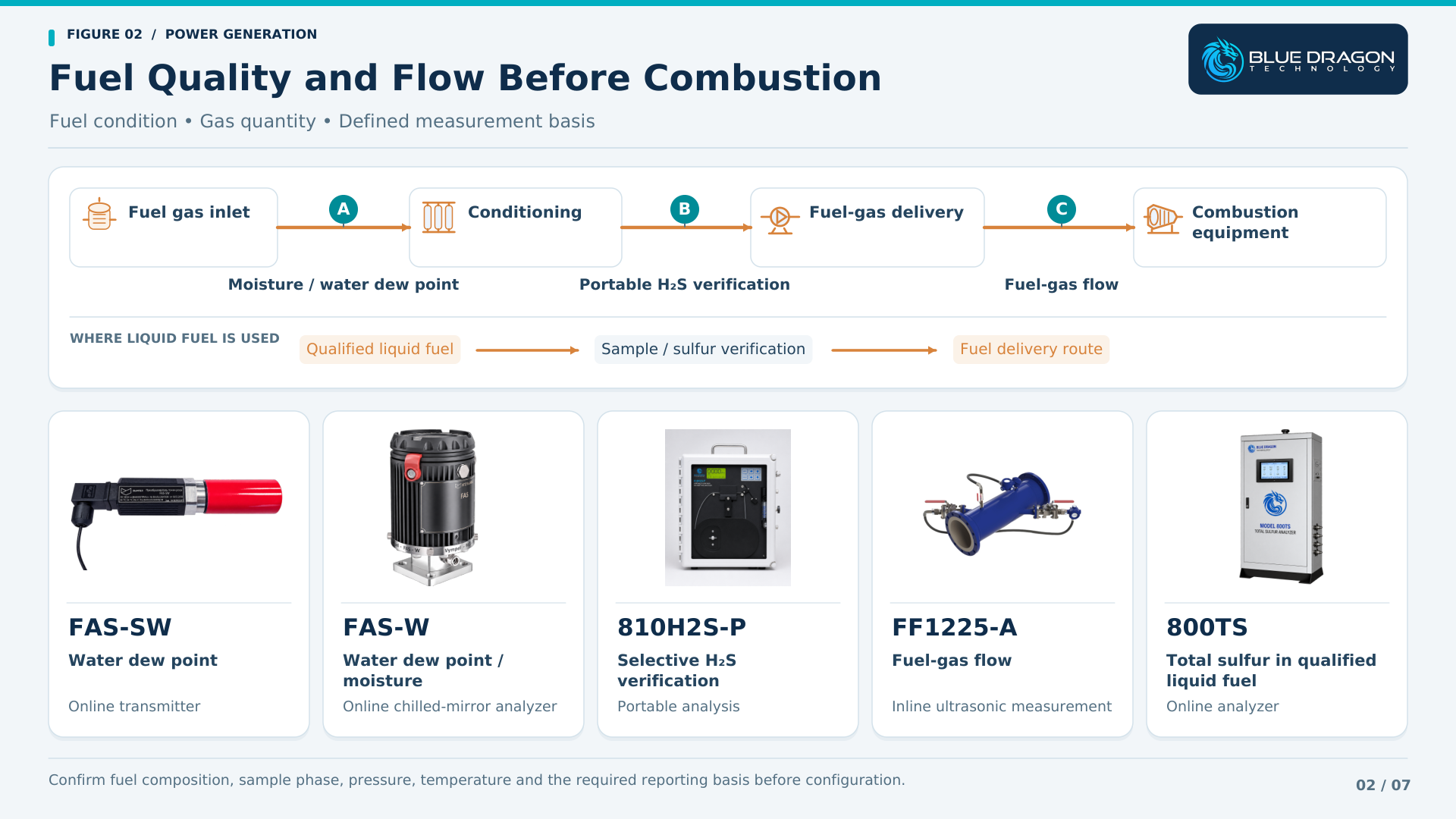
Fuel-quality and flow checks before combustion, with FAS-SW, FAS-W, 810H2S-P, FF1225-A and 800TS product images.

Figure 2. Fuel measurements before combustion address different requirements. FAS-SW and FAS-W represent alternative moisture approaches; portable H₂S verification, fuel-gas flow and qualified liquid-fuel sulfur analysis serve separate measurement tasks.

Combustion Exhaust and Flue-Gas Flow

Combustion exhaust creates a different installation challenge from a fuel-gas line. Gas temperature, duct dimensions, velocity distribution, moisture, particulate loading and available access can influence the measurement design and its maintainability.

The FF1225-XT Extreme-Temperature Ultrasonic Gas Flow Meter provides an engineered ultrasonic approach for qualified high-temperature gas-flow applications. The waveguide arrangement and measuring geometry must be matched to the actual process conditions.

Exhaust or flue-gas flow information can contribute to operating comparisons and thermal investigations when combined with the relevant temperature, composition and plant data. The useful measurement location depends on the duct layout, flow profile and the question the plant needs to answer.

  • Define normal, startup and maximum gas temperatures and pressures.
  • Review the duct or pipe geometry, velocity range and expected flow distribution.
  • Identify moisture, solids, corrosion and possible deposits.
  • Provide installation drawings, access requirements and the intended verification basis.

Gas-flow measurement establishes gas movement. Pollutant concentrations and any regulatory emissions reporting require the appropriate additional measurements, calculations and site acceptance arrangements. The proposed flow meter should be evaluated within that complete system where emissions-related use is intended.

Boiler, HRSG and Equipment Temperature Measurement

Temperature measurement becomes more useful when the physical location of the measurement is clear. External tube-wall temperature, a profile through suitable equipment and the temperature of a stationary machinery surface are different quantities. Each needs an appropriate sensing and mounting arrangement.

External Tube-Wall Temperature

The BDT-SKIN Tube-Skin Thermocouples are engineered for direct external tube-wall temperature measurement. Selected boiler, superheater and heat-recovery applications require review of tube geometry, materials, operating temperature and the surrounding thermal environment.

Measurements at defined tube locations can support comparisons between monitored areas, investigation of localized overheating and assessment of changes over time. Their interpretation should consider load, operating conditions and the limitations of the installed measurement coverage.

Attachment, thermal contact, shielding, expansion allowance, routing and termination are part of the assembly design. A representative installation must tolerate movement and the local thermal environment while maintaining the intended contact with the tube wall. Equipment drawings and installation requirements are therefore important inputs before manufacture.

Multipoint Temperature Profiles

The BDT-MP Multipoint Temperature Assemblies provide multiple thermocouple or RTD sensing points at defined positions within suitable process equipment. A profile can reveal how temperature changes with elevation, depth or another specified dimension.

The application should identify the equipment, required sensing positions and reason for measuring the profile. Insertion length, nozzle geometry, mechanical support, materials, pressure, temperature and termination requirements determine the final design. Each proposed power-plant location needs this engineering review before an assembly is assigned to it.

Equipment-Surface Temperature

The BDT-GT Gasket-Mount Surface Thermocouples provide a compact contact arrangement for suitable bolted or stud-mounted locations on stationary machinery, housings, flanges and other equipment surfaces.

These measurements can support equipment-condition trending where the surface temperature is relevant to the maintenance or operating question. Contact quality, mounting pressure, local heat transfer, vibration, cable routing and the environment must be considered. The gasket-mount product name describes the mounting architecture; the intended surface location should be specified in the application.
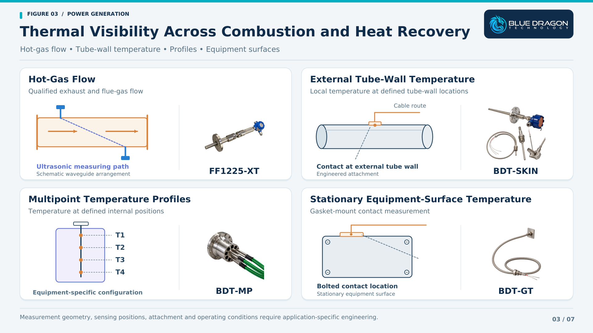
FF1225-XT, BDT-SKIN, BDT-MP and BDT-GT paired with diagrams of hot-gas flow and three temperature measurement approaches.

Figure 3. Four distinct measurement approaches support thermal-equipment assessment: qualified hot-gas flow, external tube-wall temperature, internal multipoint temperature profiles and stationary equipment-surface temperature. Measurement geometry and installation require application-specific engineering.

Water and Steam-Cycle Chemistry

The steam-water cycle carries energy through the plant under conditions that make water chemistry important to equipment operation. Makeup water, condensate, feedwater, boiler water and steam samples have different compositions and monitoring objectives. The plant chemistry program defines which measurements are needed and how their results are interpreted.

Measurement Locations Across the Cycle

Sampling locations should be selected around the plant arrangement, metallurgy, treatment regime and known contamination risks. A result from the makeup-water system cannot automatically be treated as a measurement of condensate or boiler-water condition.

Representative sampling requires attention to extraction, sample transport, cooling, pressure reduction, flow and analysis. Sample-line residence time and the delivered sample condition affect how quickly an analyzer can show a change. Instruments used at a conditioned sample station must be selected for the conditions at that station.

Complementary Chemistry Measurements

A steam-water chemistry program can include pH, specific conductivity, conductivity after cation exchange, dissolved oxygen and sodium, together with additional measurements such as degassed conductivity, silica or TOC where the plant requires them. Each parameter provides a different view of chemical condition or contamination.

The IAPWS guidance on cycle-chemistry monitoring instrumentation provides a framework for selecting monitoring points and techniques for fossil-fired, combined-cycle and industrial plants. The appropriate scope depends on plant type and treatment, with TOC identified among the additional online measurement techniques.

TOC contributes information about organic carbon within this broader framework. Chemistry targets, alarm values and operating responses should follow the plant-specific program and applicable guidance, rather than a universal number applied to every system.

TOC Monitoring and Laboratory Verification

Total organic carbon measurement is useful when the plant needs to follow organic contamination, investigate a water-quality change or verify a qualified sample. The analytical principle and sample matrix determine which TOC platform is appropriate.

Online Low-Level TOC Monitoring

The Model U1600-O Online TOC Analyzer uses UV photocatalytic oxidation and differential conductivity detection for qualified low-level, high-purity-water applications. Suitable makeup or deionized-water duties can be reviewed against the required range, conductivity and sample-delivery conditions.

Online records can help a plant follow changes between laboratory sampling events. To use those records effectively, define the sample point, transport delay, analysis timing, calibration or verification practice and the intended response to a change.

Condensate and chemically treated samples require particular attention to conductivity, treatment chemicals and method compatibility. Cooling, pressure reduction and a compatible measurement range are necessary parts of the review. Being part of a steam-water cycle does not by itself establish sample suitability for a high-purity-water analyzer.

Offline Low-Level TOC Verification

The Model U1600-L Laboratory TOC Analyzer applies the UV oxidation and differential-conductivity approach in an offline laboratory workflow for qualified low-conductivity samples.

Comparison with an online result requires suitable sampling timing and clean, compatible containers. Sample handling, background contamination, holding conditions and method differences should be considered when investigating a discrepancy. Laboratory verification becomes more useful when the sample point and collection time are recorded with the result.

Broader-Matrix Laboratory Carbon Analysis

The Model C680 High-Temperature Combustion TOC Analyzer provides a laboratory approach for qualified water and wastewater samples using catalytic combustion and NDIR carbon-dioxide detection. Separate Total Carbon and Inorganic Carbon paths support TOC calculation, with appropriate NPOC workflows available for suitable samples.

The standard C680 uses manual microsyringe injection. Its role is therefore an offline analytical workflow supporting laboratory verification, treatment assessment and investigation. Method selection, calibration, dilution, inorganic-carbon handling and matrix compatibility remain part of the laboratory procedure.
Application note: Select a TOC platform from the water matrix, conductivity, expected carbon range, sample conditions and required workflow. Online high-purity-water monitoring and broader-matrix laboratory analysis have different analytical and installation requirements.

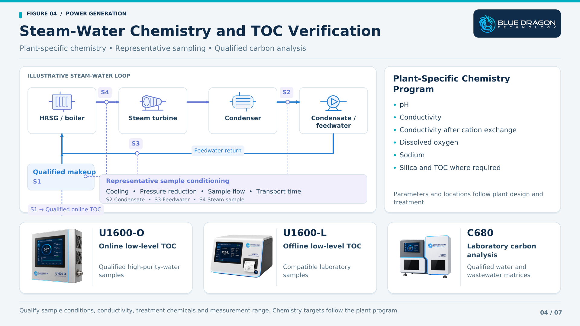
Steam-water cycle with four sampling points, sample conditioning and U1600-O, U1600-L and C680 carbon-analysis options.

Figure 4. Illustrative steam-water sampling and carbon-analysis options. The U1600-O is linked to qualified makeup water; condensate and chemically treated samples require separate suitability review. Chemistry parameters and sampling locations follow the plant program.

Cooling Water and Filtration Monitoring

Cooling and utility-water systems introduce a different set of conditions from high-purity makeup water. Incoming water can change with weather, source conditions and treatment operation. Clarification, filtration, reuse and recirculating cooling arrangements each create possible monitoring locations.

The Model C620TUR Online Turbidity Analyzer provides an optical measurement of scattering material in qualified water applications. Its self-wiping sensor and local controller support continuous turbidity indication and configured plant outputs.

At a suitable intake or treatment point, turbidity trends can help identify changing water conditions. Measurements around filtration may support investigation of treatment behavior or breakthrough. Selected cooling-water applications require confirmation of temperature, matrix, mounting and maintenance access.

Bubbles, particle size and characteristics, optical fouling, deposits and sensor position can influence the result. The monitoring point should provide a representative sample and permit routine inspection and verification. Sensor cleaning reduces normal deposit buildup while remaining part of a wider maintenance procedure.

Turbidity is reported on the instrument’s configured optical basis. Any relationship to suspended-solids concentration must be established for the actual water and particle population. Other cooling-water requirements, including dissolved chemistry and treatment control, remain part of the wider water-management program.
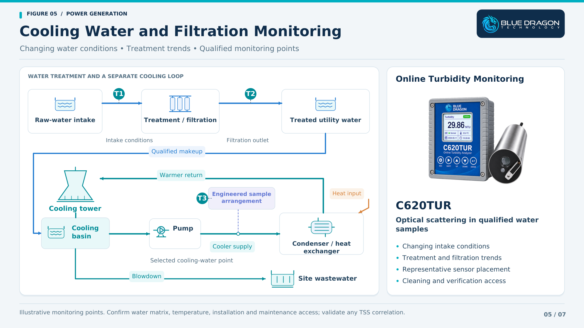
Cooling-water circuit and treatment train showing three illustrative turbidity monitoring points and the C620TUR controller and sensor.

Figure 5. Illustrative turbidity monitoring across intake water, filtration and a selected cooling-water location using the C620TUR. Pressurized services require an engineered sample arrangement, and any relationship between turbidity and total suspended solids must be validated.

Wastewater Monitoring and Laboratory Verification

Power-plant wastewater may include treatment residuals, cooling-system blowdown, equipment-area drainage and other site-specific effluents. The plant should define the contributing streams and treatment arrangement before assigning an analyzer. COD, turbidity, oil-in-water and organic carbon provide complementary information.

Chemical Oxygen Demand

The Model C630COD Online COD Analyzer measures CODCr using automatic sample handling, reagent metering, dichromate digestion and colorimetric detection. It provides repeated analytical results according to the configured measurement schedule.

COD describes oxygen demand under the selected chemical method. It can support wastewater-treatment trends and investigation where that method is suitable. Chloride background, sample variability, oxidation behavior, solids handling, reagent management and the delivered range should be reviewed with the plant. The analysis cycle and sample-transport delay determine when a new result becomes available.

Turbidity in Treatment and Discharge-Related Streams

C620TUR can provide solids-related optical trends at qualified wastewater locations. Representative placement, bubbles, fouling, cleaning and verification remain important. Results should be interpreted against the treatment process and any validated site relationship to other parameters.

Oil-in-Water Response

The Model C610OIW Online Oil-in-Water Analyzer uses UV fluorescence for hydrocarbon-related monitoring in suitable water streams. Potential plant applications include investigation of oil-bearing drainage or other qualified wastewater contamination.

Response depends on the oil type, aromatic content, calibration basis, sample matrix and optical condition. The site should establish the expected contaminants and suitable reference comparison before using the result for an operating or reporting decision.

Laboratory Organic Carbon Analysis

C680 supports laboratory carbon analysis of qualified wastewater samples. Results can help compare treatment stages, investigate an online trend or assess changes in the contributing streams, using an appropriate sample preparation and validated analytical procedure.
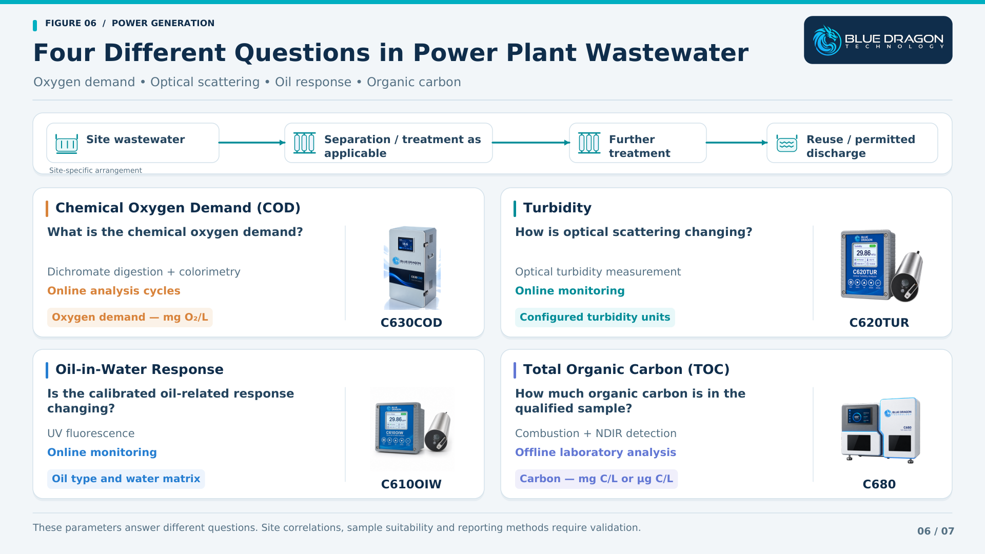
Measurement distinction: COD expresses oxygen demand, TOC expresses organic carbon, turbidity describes optical scattering, and oil-in-water fluorescence provides a calibrated hydrocarbon-related response. Any correlation between them must be demonstrated for the actual wastewater. Discharge use follows the site’s accepted methods and reporting requirements.

Four wastewater panels compare C630COD oxygen demand, C620TUR turbidity, C610OIW oil response and C680 organic carbon analysis.

Figure 6. COD, turbidity, calibrated oil response and TOC answer different wastewater questions. C630COD performs online analysis cycles, while C680 provides laboratory carbon analysis. The four parameters are not interchangeable and require separate reporting and validation.

Matching Instruments to Power Plant Areas

The following table connects representative plant areas with measurement objectives and potentially relevant technologies. It provides an application map for initial discussion. The final range, sampling system, installation and supplied configuration follow review of the actual plant requirement.

Plant Area Measurement Need Measurement Technology Representative Blue Dragon Solutions
Fuel-gas receiving and conditioning Moisture and water dew point Continuous transmitter or chilled-mirror analysis FAS-SW, FAS-W
Fuel-gas field investigation Selective H₂S verification Portable tape-based gas analysis 810H2S-P
Qualified liquid-fuel systems Total sulfur Online catalytic conversion and UV fluorescence 800TS
Fuel and process-gas lines Gas flow Inline ultrasonic gas-flow measurement FF1225-A
Qualified hot exhaust and flue-gas duties Extreme-temperature gas flow Engineered waveguide ultrasonic measurement FF1225-XT
Boiler and HRSG tubes Local external tube-wall temperature Engineered tube-skin thermocouples BDT-SKIN
Suitable equipment and stationary surfaces Temperature profiles and surface temperature Multipoint assemblies and gasket-mount thermocouples BDT-MP, BDT-GT
Qualified high-purity water Low-level TOC monitoring and verification Online and offline UV oxidation with differential conductivity U1600-O (online), U1600-L (laboratory)
Plant water and wastewater laboratory Qualified carbon analysis Laboratory combustion and NDIR detection C680 (laboratory)
Intake, filtration and cooling-water systems Turbidity Online optical turbidity measurement C620TUR
Wastewater treatment and investigation COD, turbidity, oil response and TOC Online COD cycles, optical sensors and laboratory carbon analysis C630COD, C620TUR, C610OIW; C680 (laboratory)

Technical Qualification: Why Application Review Comes First

A parameter name provides a starting point, but the actual application determines the instrument design and installation. Two gas streams requiring moisture measurement may have different pressures, contaminants and sampling needs. Two water samples requiring TOC may need different oxidation and detection methods.

A useful application review connects the measurement objective with the following engineering inputs.

1. Measurement Objective

Define the required parameter, reporting basis, range, response and intended use. Establish whether the result supports an operating trend, an investigation, laboratory verification, an alarm or another plant decision.

2. Stream Composition and Sample Matrix

Provide representative gas composition or water chemistry, including expected contaminants. Identify free liquids, particles, aerosols, oil, treatment chemicals and possible interferents that may affect measurement or sample handling.

3. Pressure and Temperature

Include normal operation, startup and upset conditions. For sampled measurements, specify both process conditions and the conditions expected at the analyzer after any cooling, pressure reduction or other conditioning.

4. Sampling and Conditioning

Review extraction, transport distance, residence time, sample flow, filtration and conditioning. Define how the system will maintain a representative sample and how total response time fits the operating requirement.

5. Installation Geometry

Provide pipe or duct dimensions, available straight runs, tube drawings, nozzles, insertion positions and mounting details. Include thermal movement, supports, sensor routing and access for installation and maintenance.

6. Materials and Installation Environment

Define wetted-material requirements, corrosion risks, ambient conditions and area classification. Certification and installation requirements should be established for the complete proposed arrangement and delivered configuration.

7. Calibration and Verification

Specify standards, reference methods, comparison procedures and record requirements. Establish maintenance intervals, consumables, cleaning arrangements and practical access for verification of the installed measurement.

8. Outputs and Plant Integration

Identify required analogue signals, digital communications, alarm functions, historian records and interface responsibilities. Any operating action or interlock requires the site-defined control and engineering basis.

Building a Coordinated Power Generation Measurement Package

A coordinated scope can begin with one defined measurement problem. Additional instruments can be reviewed where they provide information that helps the plant understand the same system or investigate connected operating conditions.

Fuel Quality and Gas Flow Package

Combine qualified moisture and water-dew-point monitoring with fuel-gas flow. Add portable H₂S verification where relevant, and liquid-fuel sulfur analysis where the fuel and analytical objective justify it. The scope follows the actual fuel supply and receiving equipment.

Thermal Equipment and Exhaust Package

Review selected tube-wall temperatures, engineered temperature profiles, stationary equipment-surface measurements and hot-gas flow. Drawings, measurement positions and operating conditions determine which assemblies and measuring arrangements are appropriate.

High-Purity Water and Laboratory Verification Package

Evaluate online low-level TOC monitoring and offline verification for compatible high-purity samples. Use a suitable laboratory carbon platform where broader water or wastewater matrices require a different analytical approach. Coordinate this scope with the plant chemistry program.

Cooling Water and Wastewater Package

Select turbidity, oil-related response, COD or laboratory TOC around defined water-treatment questions. Sampling locations, matrix compatibility, analytical timing and reference comparison determine how the measurements can support treatment and investigation.

Coordinated Plant Scope

For a wider project, combine the selected packages with a shared review of sampling, installation, utilities, communication, documentation and verification. Define the supplied scope and plant responsibilities so that each measurement has an owner, a maintenance plan and an intended use.
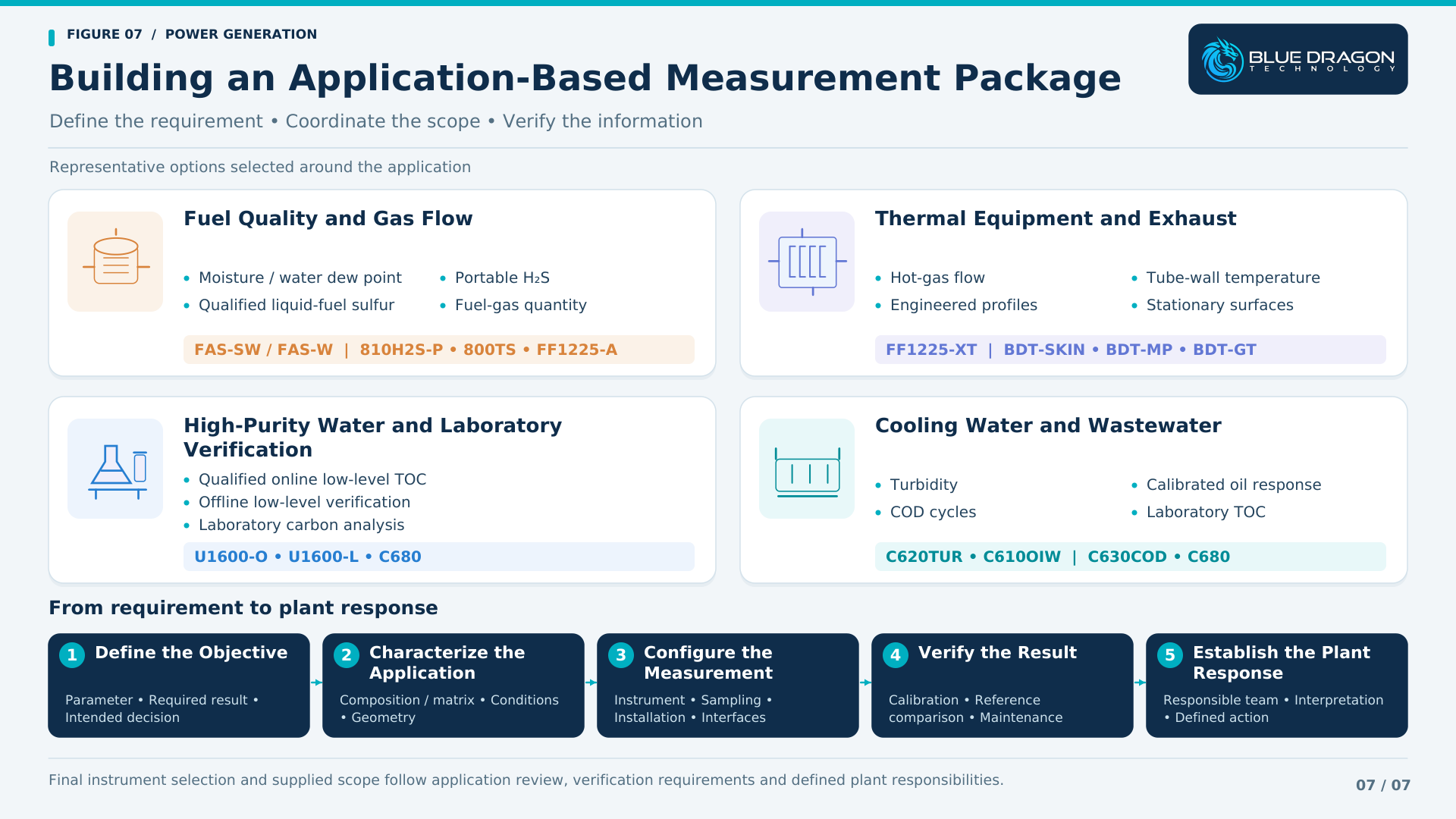
Four power-generation measurement packages above a five-step workflow from defining the objective to establishing the plant response.

Figure 7. Representative measurement options grouped around fuel and gas flow, thermal equipment, high-purity water and laboratory verification, and cooling water and wastewater. A five-step workflow connects the measurement objective with configuration, verification and a defined plant response.

Information to Provide Before Instrument Selection or Quotation

Providing the available application information at the beginning of a project helps identify suitable technologies and the questions that still need to be resolved. For an initial review, share:

  • Plant type and process or equipment area
  • Measurement objective and intended use of the result
  • Gas, liquid, water or equipment details
  • Representative composition, fuel properties or water matrix
  • Required measurement range and response
  • Normal, minimum and maximum pressure and temperature
  • Pipe, duct, tube or equipment drawings and dimensions
  • Proposed sampling arrangement and installation location
  • Materials, area classification and environmental requirements
  • Required signals, communications and documentation
  • Calibration or reference-method requirements
  • Project location and schedule

A complete specification is not necessary to begin the discussion. Blue Dragon can review the available information, identify missing inputs and define the next engineering step before final configuration and quotation.

Frequently Asked Questions About Power Generation Instrumentation

Which measurements support power generation beyond the turbine?

Relevant categories include fuel moisture and sulfur where required, gas flow, boiler and HRSG tube temperatures, engineered equipment temperatures, steam-water chemistry, cooling-water quality and wastewater analysis. The priorities depend on plant type, process conditions and the decisions the measurements must support.

What is the difference between moisture concentration and water dew point?

Moisture concentration reports the amount of water on a defined concentration basis. Water dew point reports the temperature at which water condensation begins at the stated pressure. The required output and measurement pressure should be specified when reviewing a fuel-gas application.

Where is portable H₂S verification useful?

Portable H₂S analysis can support commissioning, field verification, temporary monitoring and troubleshooting at qualified sampling points. The 810H2S-P requires a suitable sample and general-purpose, non-hazardous installation environment. A permanent online installation needs a separately defined scope.

How does fuel-gas flow differ from exhaust-gas flow measurement?

Fuel and exhaust services can differ substantially in temperature, pressure, duct or pipe geometry, flow distribution and contaminants. The measurement architecture and installation must follow those conditions. FF1225-A and FF1225-XT represent different ultrasonic configurations for qualified applications.

What do tube-skin thermocouples measure?

Tube-skin thermocouples measure local external tube-wall temperature at defined locations. BDT-SKIN assemblies are engineered around the tube geometry, attachment, thermal environment, movement and routing. The installed readings should be interpreted with the equipment operating conditions and measurement coverage.

Does TOC provide a complete steam-water chemistry assessment?

TOC provides organic-carbon information. A plant chemistry program also considers other parameters, potentially including pH, conductivity, conductivity after cation exchange, dissolved oxygen, sodium and silica. The required monitoring points and techniques depend on plant design, treatment and applicable guidance.

How do online TOC and laboratory TOC workflows differ?

Online measurement produces records from a defined sample-delivery system, while laboratory analysis tests collected samples under a controlled procedure. U1600-O and U1600-L address qualified low-level, low-conductivity samples in different workflows; C680 supports qualified laboratory combustion-based carbon analysis.

Can COD, TOC, turbidity and oil-in-water results be converted directly?

These parameters measure different properties using different methods. A site may establish a useful correlation for a defined wastewater, but it must be validated against representative samples and the intended use. Changes in composition can change that relationship.

From Fuel Conditions to Reliable Generation

Power generation brings fuel, gas movement, thermal equipment and water systems together in one operating environment. Each introduces a different measurement question, and each requires a representative installation and a suitable interpretation of the result.

  • Fuel-quality measurements help establish incoming fuel conditions.
  • Gas-flow measurements provide visibility of fuel, process-gas and qualified hot-gas movement.
  • Engineered temperature assemblies reveal local tube-wall, internal-profile and equipment-surface conditions.
  • Water-quality instruments support treatment monitoring, contamination investigation and the wider chemistry program.
  • Laboratory analysis provides complementary verification and investigation data.

The value comes from connecting the right measurement point to an operating, maintenance or water-quality decision. Sample suitability, installation, verification and a defined plant response are what make the information useful.

Blue Dragon Technology supports individual measurement requirements and coordinated scopes across fuel systems, combustion and heat recovery, qualified water applications, cooling systems and wastewater.

Discuss Your Power Generation Measurement Requirements

Blue Dragon Technology can review individual measurement points or a coordinated plant scope across fuel quality, gas flow, engineered temperature measurement, water-quality monitoring and laboratory verification.

Share the plant area, measurement objective, sample or equipment details, operating conditions, installation requirements and project schedule where available. These inputs help define the appropriate technical review and proposed configuration.

Discuss Your Application
Request a Quote
Contact Blue Dragon

Blue Dragon Technology
Measure. Control. Optimize.
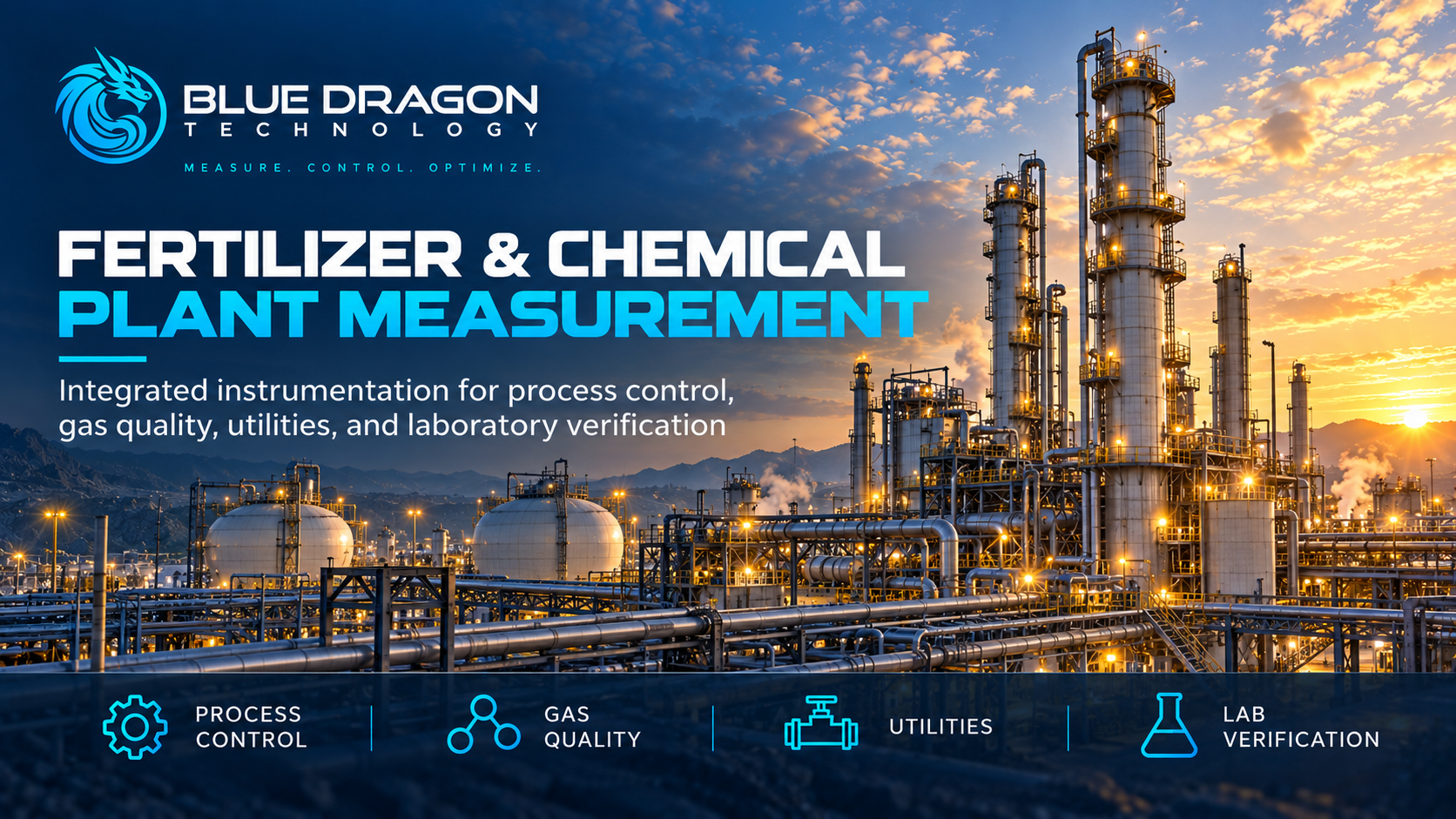
Blue Dragon Technology fertilizer and chemical plant measurement solutions for process control, gas quality, utilities, and laboratory verification.

Fertilizer & Chemical Plant Instrumentation: Measurement Solutions from Feed Gas to Finished Product

Fertilizer and chemical plants bring together several very different measurement environments within a single production complex. Feed-gas quality, sulfur, trace moisture, fired-equipment temperature, reactor temperature profiles, gas flow, raw-material composition, product quality and supporting water systems can all influence plant reliability and production decisions.

These requirements extend from natural-gas and feed preparation through reforming, synthesis and reaction, and continue into ammonia, urea, phosphate, DAP, NPK, laboratory quality control, plant utilities and wastewater systems.

There is no single analyzer or sensor that can address all of these measurement points. Effective fertilizer and chemical plant instrumentation instead requires a coordinated combination of gas analysis, moisture measurement, temperature measurement, ultrasonic gas flow, elemental analysis and water-quality instrumentation.

The central principle is simple: the instrument should be selected around the actual application—not around the model name alone. Stream chemistry, sample phase, pressure, temperature, materials, installation conditions, hazardous-area requirements and the decision the measurement must support all influence the correct configuration.

This article examines the major measurement opportunities across fertilizer and chemical production and explains how different Blue Dragon technologies can be applied from feed gas to finished product.

Fertilizer & Chemical Plant Measurement Solutions: Video Overview

The Blue Dragon Technology presentation below provides a visual overview of measurement applications across fertilizer and chemical plants, including feed-gas verification, sulfur and moisture measurement, reformer and reactor temperature monitoring, raw-material analysis, gas flow, utilities, water quality and laboratory verification.

The sections below expand on the measurement challenges introduced in the presentation and explain how the technologies fit into the process in greater technical detail.

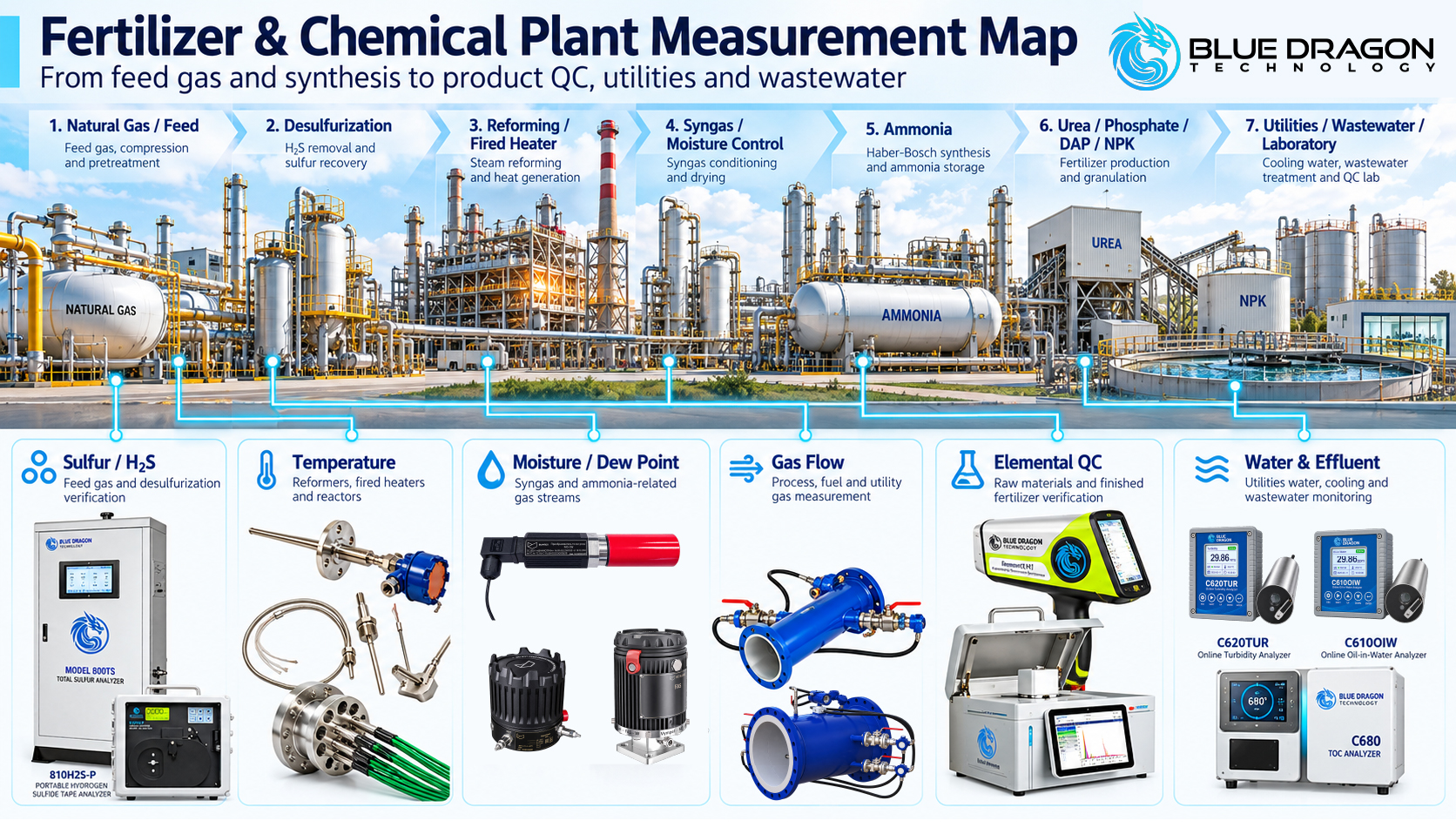
Blue Dragon fertilizer and chemical plant measurement map showing gas quality, temperature, moisture, flow, elemental QC and water monitoring across the plant.

Figure 1. A plant-wide measurement map showing where Blue Dragon instrumentation supports gas treatment, synthesis, reaction, product quality, utilities and water monitoring.

Understanding the Fertilizer & Chemical Plant Measurement Chain

A fertilizer plant is not one measurement environment. It is a sequence of processes in which the physical form of the material, the process chemistry and the operating objective can change significantly from one unit to the next.

At the front of an ammonia or urea process, the principal concern may be the quality of the incoming gas. Sulfur compounds and moisture can be important because downstream treatment, catalysts and process equipment may depend on suitably conditioned gas.

Further into the plant, reformers, fired heaters, reactors, columns and vessels create different measurement requirements. Here, external tube-wall temperature, internal temperature distribution and gas-flow behaviour may become important to plant personnel.

Phosphate, DAP and NPK production introduce another set of questions involving raw-material composition, formulation, granulation, intermediate materials and final-product verification.

Meanwhile, cooling water, process water, scrubbers, wastewater systems and plant laboratories introduce water-quality and analytical requirements that are technically separate from the main synthesis process but remain important to plant operation.

The result is best understood as an integrated measurement architecture covering gas quality, moisture, thermal conditions, flow, elemental quality control and water systems.

Feed Gas, Hydrogen Sulfide & Total Sulfur Measurement

Sulfur measurement can be relevant at several points in fertilizer and chemical processing, particularly where gas quality, catalyst protection, gas treatment or downstream process requirements depend on sulfur control.

Instrument selection should begin by identifying the sulfur species that must be measured, the sample phase, expected concentration range, stream pressure and temperature, sample-conditioning requirements and the intended use of the result.

Hydrogen Sulfide Measurement

For selective hydrogen-sulfide measurement, Blue Dragon’s sulfur-analysis portfolio includes several configurations intended for different operating requirements.

  • Model 810H2S is the online H₂S tape-analyzer configuration for continuous selective H₂S monitoring in qualified gas applications.
  • Model 810H2S-P provides portable H₂S measurement for field verification, commissioning, temporary monitoring and troubleshooting in appropriate general-purpose locations.
  • Model 810H2S-TS combines direct H₂S measurement with a separate Total Sulfur measurement path using a heated hydrogen-conversion section.

The appropriate configuration depends on whether the objective is continuous process monitoring, combined H₂S and Total Sulfur analysis, or portable verification. Final range, stream composition, sample conditioning, utilities, hazardous-area requirements and current product availability should be confirmed during application review. Availability varies by model; refer to the linked product page for the current release status.

Total Sulfur Measurement

Total sulfur answers a different analytical question from selective H₂S measurement. It is used where the plant needs to understand sulfur across the compounds converted and detected by the selected analytical method.

The Blue Dragon Model 800TS Online Total Sulfur Analyzer uses high-temperature catalytic combustion and ultraviolet fluorescence detection. The documented standard configuration is oriented toward suitable light-hydrocarbon liquid samples; gas-phase use and any fertilizer-plant application require specific confirmation of the sample and sample-handling arrangement.

Application note: H₂S, Total Sulfur and other sulfur measurements are not interchangeable. Define the target sulfur measurement, sample phase, composition, range, pressure, temperature and process objective before selecting the analyzer.

Trace Moisture & Dew-Point Measurement in Process Gas

Moisture and dew-point measurement can support gas-quality monitoring across syngas, ammonia gas and other qualified process-gas streams. The objective may be to verify dryer performance, observe moisture breakthrough, reduce condensation risk or provide greater visibility into gas condition before sensitive downstream equipment.

Blue Dragon provides several different moisture technologies because no single measurement principle is ideal for every gas composition, range or installation.

Gas composition is particularly important in moisture measurement. Reactive components, free liquids, aerosols, pressure reduction, sample-line condition and background moisture can influence both technology selection and measurement performance.

For this reason, a trace-moisture application review should establish the complete gas composition, pressure, temperature, expected range, sample-conditioning arrangement and verification method before configuration.

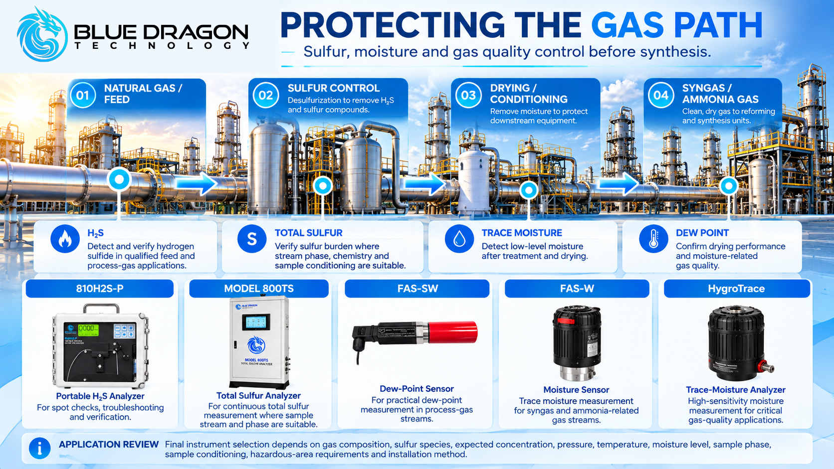
Fertilizer plant gas path showing sulfur, H2S, trace moisture and dew-point measurement before and through synthesis processes.

Figure 2. Protecting the gas path with sulfur, H₂S, trace-moisture and dew-point measurement for qualified process-gas streams.

Temperature Measurement in Reformers, Fired Heaters & Reactors

Thermal measurement requirements in fertilizer and chemical plants can be divided into at least two very different problems: measuring the external temperature of fired-equipment tubes and measuring temperature distribution at multiple internal locations within reactors or vessels.

Those two objectives require different sensor architectures.

Primary Reformer & Fired-Heater Tube-Skin Temperature

Primary reformers and fired heaters operate in demanding thermal environments where local tube-wall temperature can provide important information about operating behaviour and equipment condition.

The Blue Dragon BDT-SKIN Tube-Skin Thermocouples are engineered for direct external tube-wall temperature measurement. The complete assembly must account for tube geometry, operating temperature, attachment method, shielding, thermal expansion, routing and termination.

Representative tube-skin temperature information can support:

  • Identification of localized overheating
  • Comparison of temperature behaviour across critical tubes
  • Thermal-performance investigation
  • Maintenance and inspection planning
  • Long-term equipment-condition trending

Tube-skin thermocouples are engineered assemblies rather than generic surface sensors. Plant drawings, tube dimensions, material, monitored locations, design temperature and installation requirements should be reviewed before manufacture.

Multi-Point Reactor Temperature Profiling

Reactor measurement presents a different challenge. A single temperature point may not show how temperature varies through the depth or height of the process vessel.

The Blue Dragon BDT-MP Multipoint Temperature Assembly can be engineered with multiple thermocouple or RTD sensing points positioned at defined elevations or depths inside reactors, columns, vessels and other process equipment.

In urea and other chemical-reactor applications, multi-point measurement can help operators understand temperature distribution rather than relying on one isolated value.

The final assembly depends on vessel drawings, nozzle geometry, insertion length, sensing locations, materials, process pressure and temperature, mechanical support and termination requirements.

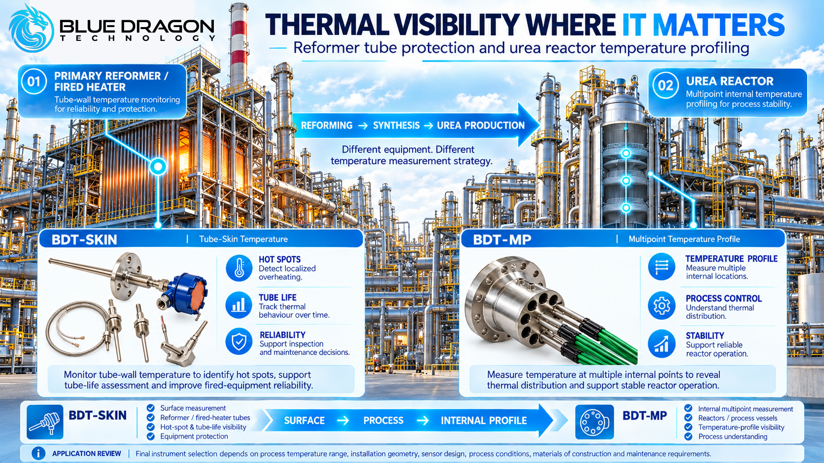
Blue Dragon BDT-SKIN and BDT-MP temperature measurement solutions for fired-heater tube monitoring and multi-point urea reactor profiling.

Figure 3. Thermal visibility where it matters: BDT-SKIN supports tube-wall temperature monitoring, while BDT-MP provides multi-point reactor temperature profiling.

The Ammonia & Urea Measurement Workflow

Viewed as one production chain, ammonia and urea manufacture can involve several measurement disciplines operating at different stages of the process.

Feed and treatment stages may require sulfur or H₂S verification where gas composition affects treatment or downstream equipment.

Primary reforming and fired equipment can require tube-wall temperature monitoring using engineered tube-skin assemblies.

Syngas and gas-conditioning stages may require moisture or dew-point measurement to understand drying performance and gas condition.

Process-gas networks may require qualified ultrasonic flow measurement where the line geometry, gas composition and required performance support that technology.

Urea reactors and related vessels may benefit from multi-point internal temperature profiling where temperature distribution is important to plant operation.

Utilities and wastewater systems introduce separate measurements including turbidity, oil-in-water and laboratory organic-carbon analysis.

These measurements do not need to come from one instrument family. Their value comes from being selected and applied as one coordinated plant measurement strategy.

Phosphate Rock, Raw Materials & Fertilizer Quality Control

Phosphate, DAP and NPK production introduce a measurement problem centred on material composition. Incoming rock, additives, intermediate materials and finished fertilizer may all require analytical verification depending on the plant’s quality-control procedures.

X-ray fluorescence spectroscopy, or XRF, provides elemental information and can be used at different stages of this workflow.

Rapid Field & Receiving Inspection

The Blue Dragon ElementX H1 Handheld XRF Spectrometer provides a portable approach to elemental screening where measurements need to be taken at receiving, storage, stockpile or other field-oriented locations.

Potential applications include screening of phosphate rock, additives and other incoming materials, subject to the installed analytical mode, calibration, sample matrix and required elements.

Laboratory Elemental Verification

The Blue Dragon ElementX B1 Vacuum Benchtop XRF Spectrometer provides a laboratory-oriented EDXRF platform for controlled elemental-analysis workflows.

The H1 and B1 therefore serve complementary roles. A plant may use rapid handheld measurements for screening and material triage while using a benchtop system for prepared samples and more structured laboratory verification.

Quantitative XRF performance depends on the sample matrix, preparation method, installed calibration and suitable reference materials. Instrument selection should therefore begin with the analytical question the plant needs to answer rather than simply the sample name.

DAP & NPK Production

For DAP and NPK production, elemental analysis can support incoming-material evaluation, formulation checks and finished-product quality-control workflows. Temperature measurement may also be relevant at selected process points where thermal conditions influence operation, but the sensor design must be matched to the actual equipment rather than assumed from the process name alone.

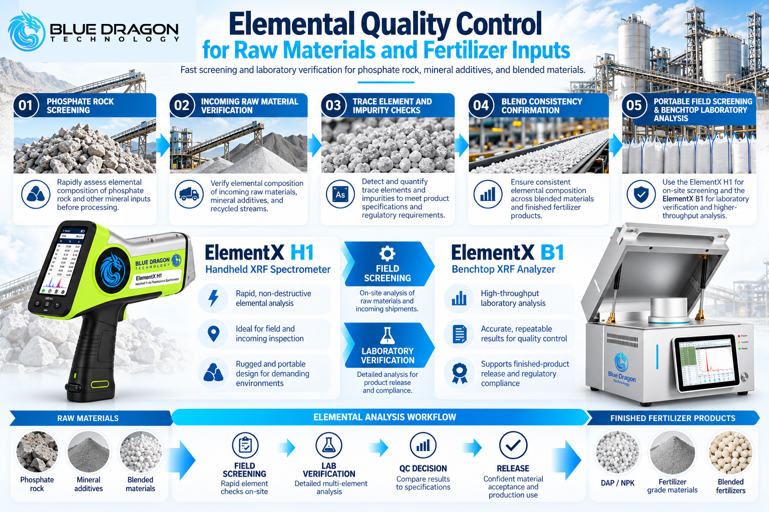
Blue Dragon ElementX H1 handheld XRF and ElementX B1 benchtop analyzer supporting elemental quality control from phosphate rock to finished fertilizer.

Figure 4. From phosphate rock to finished fertilizer: ElementX H1 provides rapid screening while ElementX B1 supports structured laboratory verification.

Phosphoric Acid, Sulfuric Acid & Reactor-Area Measurement

Acid-production and reactor areas require especially careful application review because process chemistry, corrosion, temperature and material compatibility can substantially change the measurement approach.

Potential measurement requirements can include:

  • Multi-point reactor or vessel temperature
  • Qualified gas-flow measurement
  • Utility-water and cooling-water monitoring
  • Turbidity or solids-related water trends
  • Oil contamination in appropriate water streams
  • Laboratory TOC analysis of suitable water samples

The process stream itself and the surrounding utility systems should be treated separately. A water-quality instrument appropriate for cooling or wastewater service should not be assumed to be compatible with concentrated acid or another aggressive process stream.

Important sulfur-application distinction: The Model 800RS sulfur-ratio analyzer is intended for Claus sulfur-recovery-unit tail-gas H₂S/SO₂ ratio applications. It should not be positioned as a general sulfuric-acid-production analyzer. Sulfuric-acid plant service and Claus SRU tail-gas service are different applications and require separate qualification.

Process, Fuel, Vent & Utility Gas Flow Measurement

Gas movement is another important measurement category across fertilizer and chemical plants. Depending on the process configuration, flow measurement may be required in fuel gas, process gas, vent gas, natural gas or other plant gas services.

Blue Dragon’s ultrasonic gas-flow portfolio includes inline and insertion configurations for different gas-flow applications.

Representative options include the Lauris FF1225-A Single-Path Inline Ultrasonic Gas Flow Meter and the Lauris FF2225-A Dual-Path Inline Ultrasonic Gas Flow Meter.

The appropriate flow-meter architecture cannot be selected from gas type alone. Important factors include:

  • Pipe diameter and schedule
  • Gas composition and density
  • Normal, minimum and maximum velocity
  • Pressure and temperature
  • Available straight-run distance
  • Liquid carryover or contamination
  • Required measurement uncertainty
  • Installation and transducer-access requirements
  • Hazardous-area classification and project certification

A process-gas flow application review should therefore be completed before the final meter geometry and configuration are selected.

Process Water, Cooling Water & Wastewater Monitoring

Water systems cross many areas of fertilizer and chemical plants. The exact arrangement varies by facility, but measurement requirements may arise in process water, cooling circuits, scrubbers, treatment systems, wastewater and discharge-related monitoring.

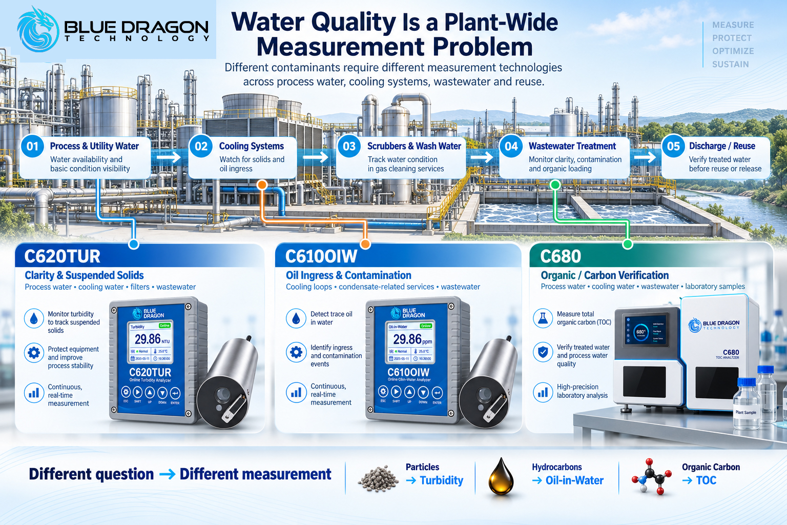
Different water-quality problems require different measurement principles. Turbidity, oil contamination and organic carbon should not be treated as interchangeable parameters.

Turbidity Monitoring

Turbidity provides an optical indication of suspended and scattering material in water. The Blue Dragon C620TUR Online Turbidity Analyzer is designed for continuous industrial water applications including process water, treatment systems, utility water and wastewater where the range and matrix are appropriate.

Measurement location, bubbles, particle characteristics, fouling, immersion conditions and calibration or verification practice can all influence turbidity performance.

Oil-in-Water Monitoring

Oil contamination represents a different water-quality problem. The Blue Dragon C610OIW Online Oil-in-Water Analyzer uses UV fluorescence for continuous oil-related trending in qualified industrial water streams.

Potential applications may include cooling-water contamination investigation, industrial wastewater and other water systems where the oil type, measurement range and sample characteristics are compatible with the sensing method.

Laboratory Total Organic Carbon Analysis

Total organic carbon provides another view of water condition by measuring carbon associated with organic material using the selected analytical method.

The Blue Dragon Model C680 High-Temperature Combustion TOC Analyzer is a laboratory instrument for TOC, TC, IC and NPOC analysis in suitable water samples using high-temperature catalytic combustion and NDIR detection.

The standard C680 configuration uses manual microsyringe injection, so it should be considered an offline laboratory analytical platform rather than an online continuous process analyzer.

Blue Dragon C620TUR, C610OIW and C680 analyzers for turbidity, oil-in-water and TOC monitoring across plant water and wastewater systems.

Figure 5. Water quality is a plant-wide measurement problem, spanning process water, cooling systems and wastewater through turbidity, oil-in-water and TOC monitoring.

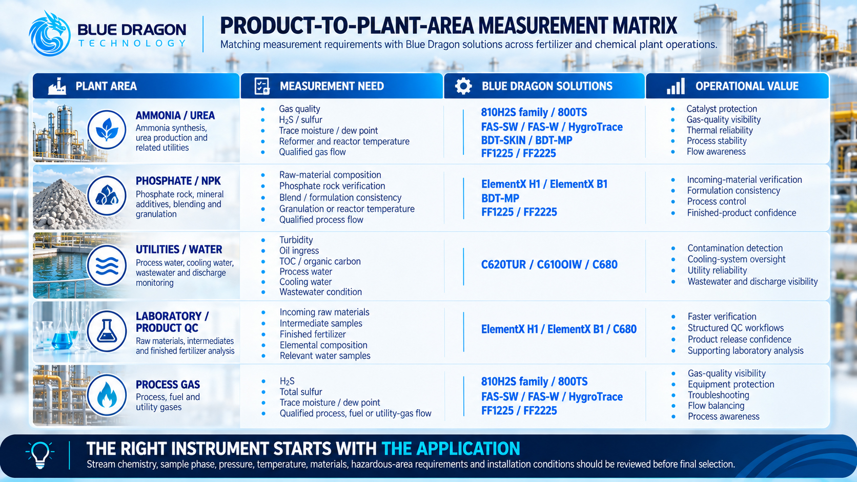
Matching Measurement Requirements to Plant Areas

The following table summarizes representative measurement requirements across the plant. It is intended as an application map rather than a universal specification. Final suitability depends on the actual process, range, chemistry, installation and project requirements.

Plant Area Measurement Need Measurement Technology Representative Blue Dragon Solutions
Ammonia / Urea Gas quality, sulfur, moisture, reformer temperature, reactor temperature and qualified gas flow H₂S / sulfur analysis, moisture and dew point, tube-skin temperature, multipoint temperature, ultrasonic gas flow 810H2S-P,
FAS-SW,
FAS-W,
HygroTrace,
BDT-SKIN,
BDT-MP
Phosphate / DAP / NPK Raw-material composition, incoming inspection, laboratory verification and finished-product QC Handheld and benchtop XRF; application-specific process temperature measurement ElementX H1,
ElementX B1,
BDT-MP where the equipment and application justify multipoint profiling
Utilities / Water Turbidity, oil contamination, water treatment and laboratory organic-carbon analysis Optical turbidity, UV-fluorescence oil-in-water, high-temperature combustion TOC C620TUR,
C610OIW,
C680
Laboratory / Product QC Incoming material, intermediate and final-product elemental analysis; relevant water-sample analysis XRF elemental analysis and laboratory TOC analysis ElementX H1,
ElementX B1,
C680
Process Gas H₂S, sulfur, moisture, dew point and qualified gas flow Tape-based H₂S, total sulfur, chilled-mirror / transmitter / coulometric moisture, ultrasonic gas flow 810H2S,
810H2S-TS,
FAS-SW,
HygroTrace,
Blue Dragon Flow Portfolio
Application note: Product-to-plant relationships identify potentially relevant technologies. They do not replace application engineering. Sample composition, phase, range, process conditions, installation, certification and required performance can change the correct solution.

Matrix connecting fertilizer and chemical plant areas with Blue Dragon gas quality, temperature, flow, elemental QC and water measurement solutions.

Figure 6. Product-to-plant-area measurement matrix showing how instrumentation is matched to ammonia and urea, phosphate and NPK, utilities, laboratory QC and process-gas applications.

Technical Qualification: Why Application Review Comes First

Industrial instrumentation should be selected around the process conditions and measurement objective rather than only around the parameter name.

Two streams may both require H₂S measurement, for example, while differing substantially in pressure, moisture, composition, required range, hazardous-area classification and sample-system design. The same principle applies to temperature, flow, elemental analysis and water-quality instrumentation.

Before final instrument selection, the following areas should normally be reviewed.

1. Gas or Process Composition

Define the target species, major stream components, possible interferents, concentration range and any reactive, corrosive or contaminating components that may affect the measurement system.

2. Sample Matrix & Phase

Confirm whether the sample is a gas, liquid, water, solid, powder or prepared laboratory sample. Free liquids, particulates, moisture, aerosols and sample preparation can materially change measurement performance.

3. Pressure & Temperature

Normal, minimum, maximum, startup and upset conditions should be considered. Pressure reduction, cooling, heat tracing or other conditioning may be necessary depending on the technology.

4. Materials & Corrosion

Wetted-material compatibility is essential in chemical service. Acids, chlorides, sulfur compounds, solvents and other aggressive components must be reviewed against the proposed sensor, sample system and process interface.

5. Hazardous-Area Requirements

Area classification, required electrical approvals, installation method, purge requirements and project certification should be defined before final configuration.

6. Calibration, Verification & Maintenance

The plant should define how the measurement will be calibrated or verified, which standards or comparison methods are required, how frequently maintenance can be performed and how the instrument will be accessed safely.

7. Installation Geometry & Process Interface

Line size, nozzles, insertion depth, straight runs, vessel geometry, mounting orientation, sensor routing and available maintenance access can be decisive—particularly for flow meters and inserted temperature assemblies.

8. Data, Outputs & Control-System Integration

Required analogue outputs, digital communications, alarms, historian data, control-system tags and ownership of any process action should be defined as part of the instrumentation scope.

Blue Dragon provides a dedicated application-engineering review for projects where the measurement point, sample, configuration or project requirements need to be qualified before quotation.

Building a Coordinated Fertilizer & Chemical Plant Measurement Package

A coordinated instrumentation package does not need to begin as a full-plant project. Plants can start with one defined measurement problem and expand the scope where additional measurements provide useful process, quality or reliability information.

Gas Quality Package

A gas-quality scope can combine H₂S or Total Sulfur measurement with moisture and dew-point monitoring for qualified feed, fuel, syngas or process-gas streams. The exact analyzer combination depends on the stream chemistry and measurement objective.

Reactor & Heater Package

BDT-SKIN and BDT-MP address two complementary temperature problems: external tube-wall monitoring on fired equipment and internal multi-point temperature profiling within reactors, columns and vessels.

Raw Material & Laboratory QC Package

ElementX H1 and ElementX B1 can provide a field-to-laboratory elemental-analysis workflow, while laboratory TOC measurement can be added where suitable plant-water or wastewater samples require carbon analysis.

Utilities & Water Package

C620TUR, C610OIW and C680 address different water-quality questions across continuous turbidity, oil-related contamination monitoring and laboratory carbon analysis.

Full Plant Measurement Package

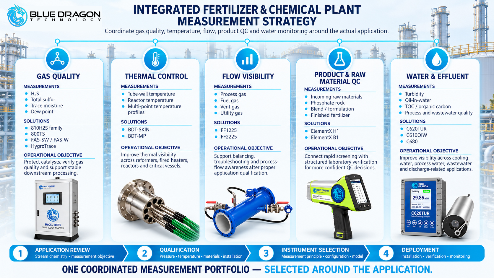
For larger projects, gas quality, temperature, flow, elemental QC and water-quality instrumentation can be evaluated together. The objective is not to install every available instrument, but to coordinate the measurements that address the plant’s actual process and quality requirements.

Integrated Blue Dragon measurement strategy covering gas quality, thermal control, flow, product QC and water monitoring from application review through deployment.

Figure 7. An integrated measurement strategy coordinating gas quality, temperature, flow, product and raw-material QC, and water monitoring around the actual application.

Information to Provide Before Instrument Selection or Quotation

Providing a small amount of application information at the beginning of a project can significantly improve instrument selection and reduce unnecessary clarification later.

Where available, provide:

  • Process or plant area
  • Measurement objective
  • Gas, liquid, water, solid or sample type
  • Complete or representative composition
  • Normal and maximum measurement range
  • Process pressure and temperature
  • Line, vessel or installation dimensions
  • Wetted-material or corrosion requirements
  • Hazardous-area classification
  • Required signals or communication protocol
  • Calibration or reference-method requirements
  • Project location and schedule

A complete specification is not necessary for an initial discussion. Blue Dragon can use the available information to identify missing qualification points and determine the appropriate technical next step.

Frequently Asked Questions About Fertilizer & Chemical Plant Instrumentation

Which measurements are commonly required in fertilizer and chemical plants?

Requirements depend on the plant and process, but relevant measurement categories can include sulfur and H₂S, trace moisture and dew point, reactor and fired-equipment temperature, process-gas flow, elemental composition, turbidity, oil-in-water and organic carbon. The correct priorities depend on the process and decisions the data must support.

How can H₂S and sulfur be monitored in fertilizer-plant gas streams?

Selective H₂S and Total Sulfur are different measurements. Blue Dragon provides tape-based H₂S configurations, combined H₂S / Total Sulfur configurations and total-sulfur analysis platforms. Stream composition, phase, range, pressure, temperature, sample conditioning and measurement objective must be reviewed before selection.

How is moisture measured in syngas or ammonia-related process gas?

Possible technologies include dew-point transmitters, chilled-mirror analyzers and coulometric ultra-trace moisture measurement. The most suitable principle depends on gas composition, pressure, moisture range, contaminants, sample conditioning, required response and verification method.

What is the difference between tube-skin and multipoint temperature measurement?

Tube-skin thermocouples measure external tube-wall temperature at defined points on fired equipment. Multipoint assemblies measure temperature at several internal elevations or depths inside reactors, columns or vessels. They solve different thermal-measurement problems and require different mechanical designs.

How can phosphate rock and finished fertilizer be analyzed?

XRF can support elemental analysis of phosphate rock, additives, prepared samples and finished fertilizer where the elements, matrix, calibration and sample preparation are suitable. Handheld XRF supports rapid field screening, while benchtop XRF supports controlled laboratory workflows.

Which measurements can be used in fertilizer-plant water systems?

Depending on the water system, measurements can include turbidity for solids-related optical trends, oil-in-water for hydrocarbon contamination and laboratory TOC analysis for organic-carbon evaluation. Each parameter answers a different analytical question.

Can the Model 800RS be used as a sulfuric-acid-production analyzer?

The Model 800RS is intended for H₂S / SO₂ ratio and air-demand monitoring in Claus sulfur-recovery-unit tail gas. That application is different from normal sulfuric-acid-production service and should not be treated as interchangeable without a separate technical review.

Why is an application review required before instrument selection?

Industrial measurements depend on more than the parameter name. Composition, sample phase, range, pressure, temperature, materials, installation geometry, hazardous-area requirements, calibration, maintenance and data integration can all change which technology and configuration are appropriate.

From Feed Gas to Finished Fertilizer

Fertilizer and chemical production combines gas treatment, synthesis, high-temperature equipment, reactors, raw materials, product-quality workflows and supporting utility systems. Each area creates a different measurement challenge.

The strongest instrumentation strategy is therefore not necessarily the one with the greatest number of instruments. It is the one that places the right measurement at the right process point and provides information that can support an operating, quality or maintenance decision.

That can mean combining:

  • Gas-quality measurement for H₂S, sulfur, moisture and dew point
  • Temperature measurement for reformer tubes, fired equipment, reactors and vessels
  • Ultrasonic gas-flow measurement for suitable process, fuel, vent and utility-gas services
  • Elemental analysis for raw-material and finished-product quality control
  • Water-quality instrumentation for turbidity, oil contamination and organic-carbon analysis

Together, these measurements provide a broader view of the process than any one instrument can provide independently.

Blue Dragon Technology supports individual measurement points and coordinated instrumentation requirements across fertilizer and chemical processing, from feed-gas verification through synthesis, reactors, product QC, utilities and wastewater.

Discuss Your Fertilizer & Chemical Plant Measurement Requirements

Blue Dragon Technology can review individual measurement points or broader plant instrumentation requirements across gas quality, sulfur, moisture, temperature, flow, raw-material and product QC, water quality and laboratory analysis.

For the most useful application review, provide the process or stream, measurement objective, expected range, composition or matrix, pressure, temperature, installation conditions, hazardous-area requirements and project schedule where available.

Discuss Your Application
Request a Quote
Contact Blue Dragon

Blue Dragon Technology
Measure. Monitor. Optimize.

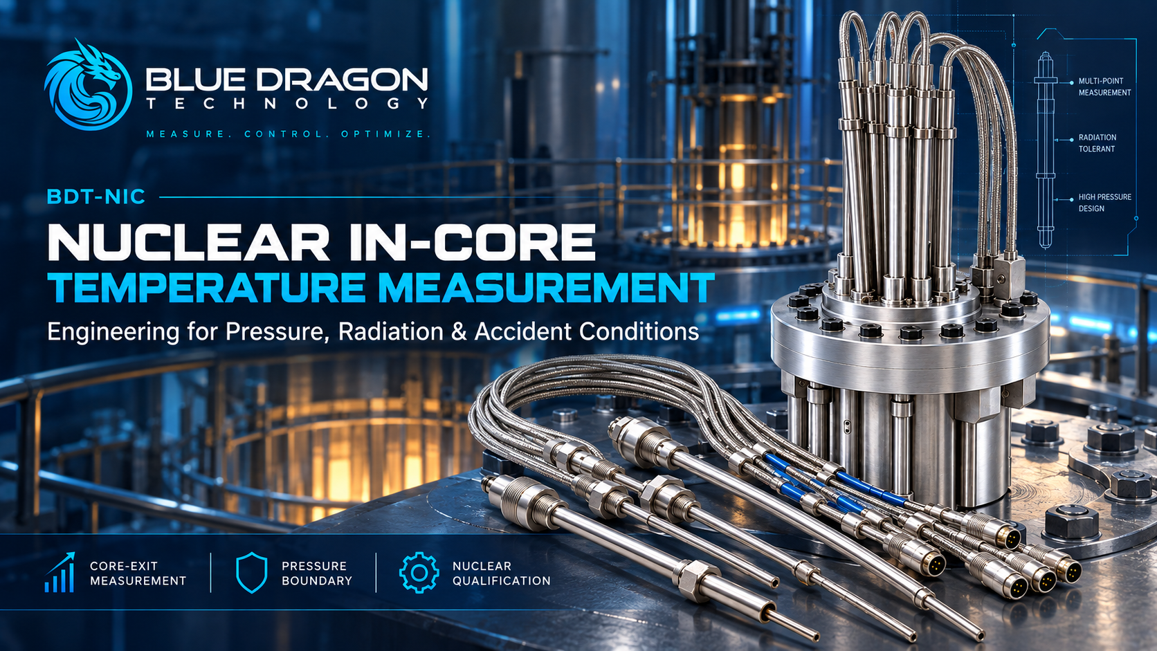
Blue Dragon Technology BDT-NIC nuclear in-core temperature measurement system with mineral-insulated thermocouple assemblies for core-exit measurement, pressure-boundary applications and nuclear qualification.

Core-Exit Temperature Measurement in Nuclear Reactors: Engineering Thermocouples for Pressure, Radiation and Accident Conditions

A thermocouple is one of the most established temperature-sensing technologies in industry. Its operating principle is straightforward: two dissimilar conductors generate a thermoelectric voltage related to the temperature difference between the measuring junction and the reference junction.

Inside or immediately above a nuclear reactor core, however, the measurement problem is no longer defined by the thermocouple alone. The sensing element may need to operate alongside reactor pressure, neutron and gamma radiation, mechanical loads, long cable runs, reactor-specific penetrations, safety-class requirements and plant instrumentation interfaces.

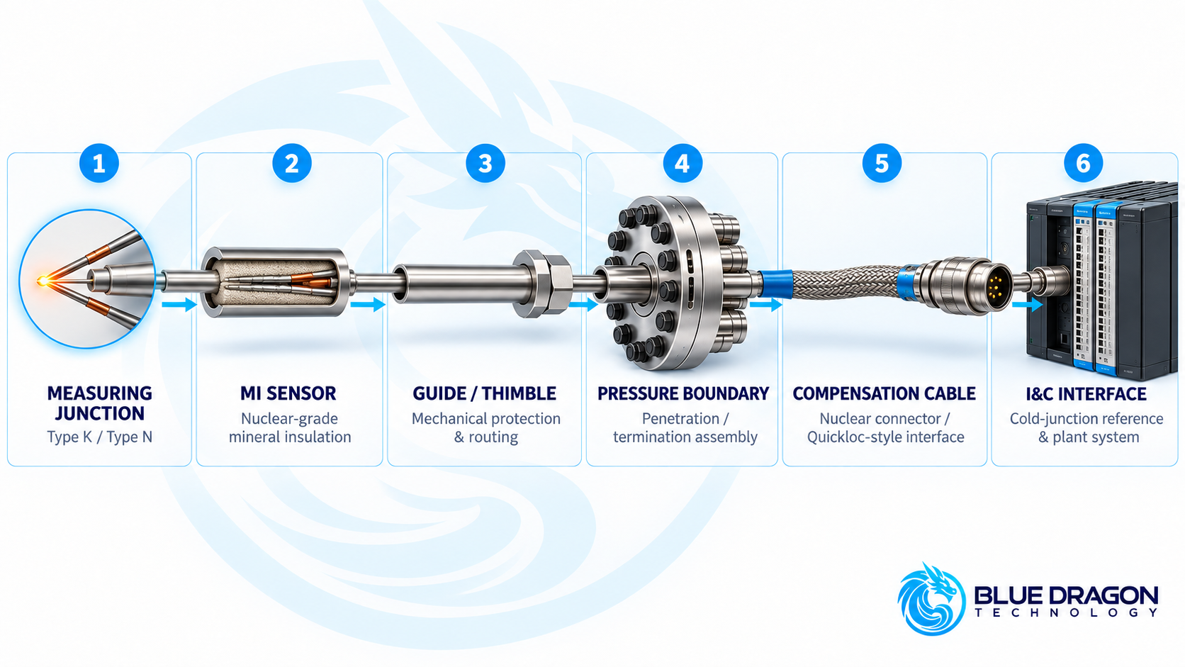
The relevant engineering object is therefore the complete temperature-measurement chain: from the measuring junction and mineral-insulated sensor through the guide, pressure boundary and compensation cable to the plant instrumentation and control system.

This article examines how nuclear core-exit and in-core temperature measurement systems are engineered around temperature capability, accuracy, response time, radiation environment, pressure containment, materials, service life and environmental qualification—and why these parameters must ultimately be defined for the specific reactor and measurement function. Blue Dragon addresses these project-specific applications through its BDT-NIC Nuclear In-Core Temperature Measurement Systems.

From Hot Junction to Plant I&C: The Complete Measurement Chain

A nuclear temperature measurement does not stop at the hot junction. The signal must travel through a mechanically and electrically controlled path before it becomes useful information inside the plant instrumentation system.

A representative measurement chain can include:

  • Measuring junction — the thermoelectric sensing point
  • Mineral-insulated thermocouple — providing compact, protected signal conductors inside a metallic sheath
  • Guide or thimble — routing and mechanically protecting the sensing assembly
  • Engineered pressure boundary — separating reactor/process pressure from the instrumentation side
  • Compensation cable and termination — carrying the thermocouple signal beyond the penetration
  • Plant I&C interface — including the appropriate cold-junction reference and measurement electronics

Representative nuclear core-exit temperature measurement chain showing the thermocouple junction, mineral-insulated sensor, guide or thimble, pressure boundary, compensation cable and plant I&C interface.

Representative nuclear temperature measurement chain extending from the sensing junction through the mineral-insulated assembly, mechanical guide and engineered pressure boundary to the compensation cable and plant I&C interface.

Mineral-Insulated Construction

Mineral-insulated, or MI, thermocouples place the thermoelement conductors inside a metallic sheath surrounded by compacted electrical insulation. This construction provides a small cross-section while mechanically protecting the conductors and maintaining electrical insulation along the sensor length.

For nuclear core-exit applications, Type K is an established reference thermocouple configuration, while Type N can be considered where required by the project. Depending on the design and qualification basis, sheath materials can include Inconel 600, 316 stainless steel or 304L stainless steel, with mineral insulation such as MgO or Al₂O₃.

Grounded and ungrounded junction arrangements can also be engineered according to the required electrical isolation, response and plant interface.

Temperature Capability Is Not the Same as Qualified Operating Range

One of the most important distinctions in nuclear temperature instrumentation is the difference between the temperature capability of the thermoelectric materials and the qualified operating range of the complete installed assembly.

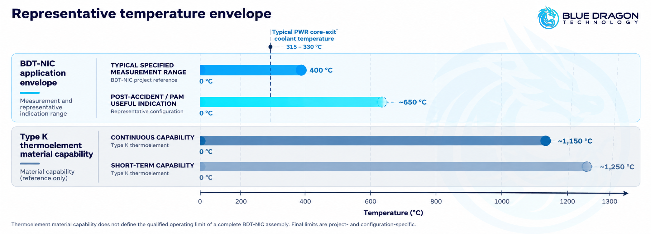
For representative nuclear-grade Type K core-exit configurations, several different temperature ranges may be relevant:

  • Typical PWR core-exit coolant environment: approximately 315–330 °C
  • Typical specified measurement range: 0 to +400 °C, extendable according to calibration and configuration
  • Representative post-accident / PAM indication: useful indication through approximately 650 °C for applicable configurations
  • Type K thermoelement continuous capability: up to approximately 1,150 °C
  • Type K short-term thermoelement capability: approximately 1,250 °C

Representative BDT-NIC temperature envelope showing typical 0 to 400 °C measurement range, approximately 315 to 330 °C PWR core-exit coolant temperature, post-accident indication around 650 °C, and Type K thermoelement capability.

Normal measurement range, representative post-accident indication and thermoelement material capability describe different engineering limits and should not be treated as interchangeable.

The thermoelement material may therefore tolerate a substantially higher temperature than the complete installed system is specified or qualified to measure.

The actual assembly limit depends on factors such as sheath alloy, sheath diameter, mineral insulation, mechanical geometry, pressure-boundary arrangement, cable and termination design, calibration and the required measurement mission.

Engineering distinction: The Seebeck pair alone does not define the qualified operating temperature of a nuclear thermocouple assembly. Final limits belong to the complete, project-specific measurement system.

Accuracy and Response Are System Properties

Reference Type K Performance

For a Type K Class 1 thermocouple, a representative reference tolerance is approximately ±1.5 °C to 375 °C, followed by approximately ±0.4% of reading over the applicable higher-temperature range.

The uncertainty of the complete installed chain is different from the tolerance of the thermocouple element alone. Around a representative PWR core-exit temperature of approximately 325 °C, a complete nuclear measurement chain may typically be around ±2 to ±2.5 °C, depending on the configuration.

Response Time Changes After Installation

A small-diameter mineral-insulated element can achieve a representative t50 response of approximately two seconds. Once that element is incorporated into an engineered reactor assembly, however, the surrounding finger, guide, sheath, mechanical protection and thermal coupling influence how quickly the final system responds.

Installed core-exit or IITA-type configurations may therefore respond over several seconds to tens of seconds, depending on the mechanical design.

This illustrates another recurring principle in nuclear instrumentation: performance must be evaluated at the system level, not simply from the properties of the bare sensing element.

Radiation Duty Depends on Where the Sensor Is Located

The term “in-core” can easily suggest that every sensor experiences the peak neutron environment inside the active core. In practice, radiation duty depends strongly on the actual measurement location.

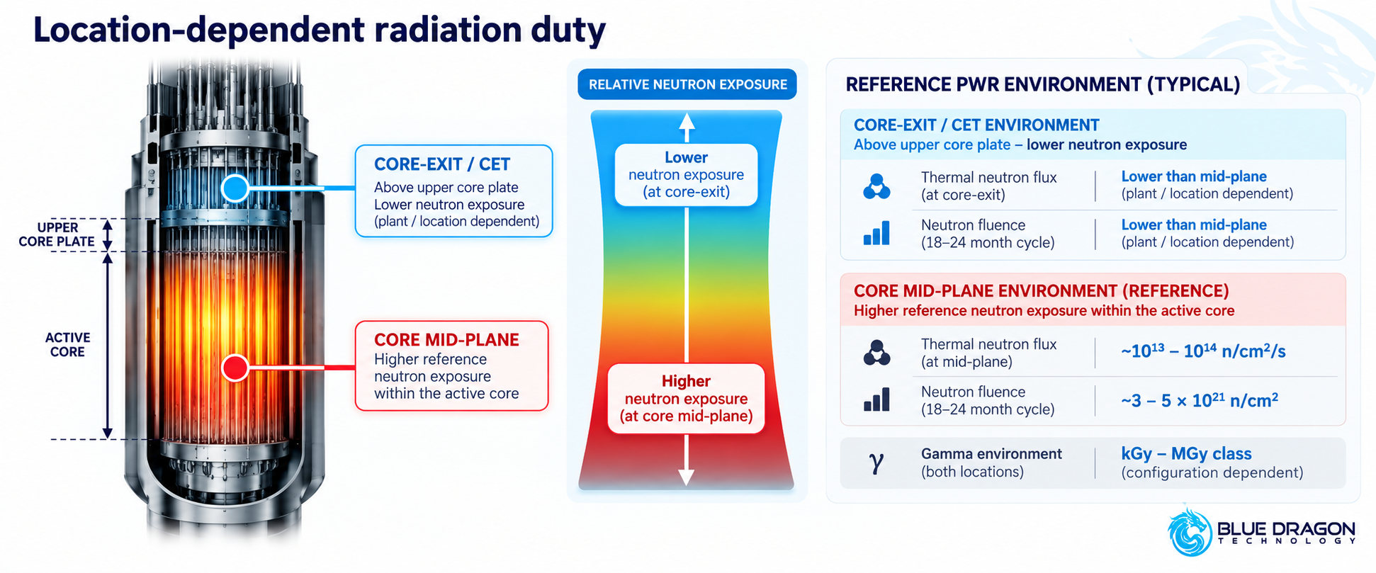
Core-exit thermocouples are positioned above the upper core plate rather than at the core mid-plane. Their neutron exposure is therefore different from the higher reference neutron environment within the active core, although gamma exposure remains a significant qualification consideration.

For context, representative PWR mid-plane conditions can be of the order of:

  • Thermal neutron flux: approximately 1013–1014 n/cm²/s
  • Thermal fluence per 18–24 month cycle: approximately 3–5 × 10²¹ n/cm²
  • Core-exit neutron exposure: lower than the core mid-plane and dependent on plant and sensor location
  • Gamma environment: potentially kGy–MGy class, depending on the configuration and location

Conceptual comparison of neutron and gamma radiation environments at the reactor core mid-plane and core-exit thermocouple location.

Core-exit thermocouples operate in a different neutron environment from the core mid-plane, while gamma exposure remains an important project-specific qualification consideration.

Radiation Influences More Than Immediate Survivability

Long-term exposure can influence thermoelectric stability, measurement drift, insulation performance, sheath condition and other components within the measurement chain.

This is why a generic neutron-flux or gamma-dose number should not be treated as a universal thermocouple rating. The relevant radiation duty has to be established at the actual sensor location and assessed within the applicable plant environmental-qualification basis.

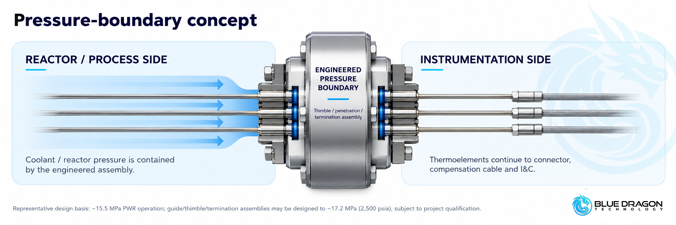
The Thermocouple Is Not the Reactor Pressure Boundary

Pressure is another area where the distinction between the sensor and the measurement system becomes important.

A large pressurized-water reactor can operate at reactor coolant system pressures around 15.5 MPa. Representative engineered IITA, guide or Quickloc-style pressure-boundary arrangements can be designed around approximately 17.2 MPa / 2,500 psia at 343 °C / 650 °F, subject to the actual project requirements.

The thermoelement itself is not the reactor coolant pressure boundary.

Pressure containment is provided by the engineered mechanical architecture around the sensing path, such as the thimble, guide, penetration, termination assembly and welded pressure-retaining components.

Conceptual nuclear thermocouple pressure-boundary arrangement showing reactor-side pressure contained by an engineered thimble, guide or termination assembly while the thermocouple signal continues to plant instrumentation.

The thermocouple provides the measurement path while reactor or process pressure is contained by the engineered guide, penetration or termination assembly.

Pressure Integrity Becomes Part of Instrument Qualification

Depending on the design and purchase specification, pressure-boundary verification can include all-welded construction, hydrostatic pressure testing, helium leak testing, weld inspection and other integrity checks.

The result is not simply a thermocouple capable of sensing temperature. It is a temperature-measurement system engineered to coexist with the mechanical boundary of the reactor installation.

Mechanical Design Is Reactor-Specific

The sensing element itself may be only a few millimetres in diameter, while the complete measurement path can extend through reactor internals, the vessel head, penetrations and cable routing over substantial distances.

Representative nuclear MI configurations can include:

  • MI sheath outside diameter: approximately 1.0–3.2 mm
  • Compact combined configurations: commonly around 1.0–1.6 mm
  • Overall length: engineered to the routing and potentially extending tens of metres
  • Sheath materials: Inconel 600, 316 stainless steel or 304L stainless steel
  • Junction arrangement: grounded or ungrounded depending on the measurement and isolation requirement

Final diameter and length are determined by the instrument-tube or thimble geometry, reactor internals, penetration arrangement, connector interface and routing to the plant instrumentation system.

Different Measurement Functions Produce Different Architectures

A project-engineered platform such as BDT-NIC can take different forms according to what the plant needs to measure.

  • Single core-exit temperature measurement for an individual monitoring location
  • Multipoint assemblies where several measurement locations are required within an engineered arrangement
  • Shared in-core instrumentation where temperature and neutron instrumentation occupy the same mechanical instrumentation space
  • Post-accident monitoring configurations engineered for the applicable safety and accident-monitoring function

These are configuration families rather than universally interchangeable products. Reactor design, sensor location, mechanical interfaces, electrical separation and qualification requirements determine the final architecture.

Core-Exit Temperature Measurement Has a Specific Plant Function

Core-exit thermocouples should not automatically be treated as interchangeable with every other reactor temperature measurement.

Depending on the plant architecture and safety basis, core-exit temperature information can support functions such as:

  • Core-exit temperature monitoring
  • Radial temperature mapping
  • Temperature or enthalpy-related monitoring
  • Post-accident indication where required by the plant design

These functions are different from temperature measurements performed elsewhere in the reactor coolant system and should not automatically be equated with loop RTD measurements used within reactor-protection calculations.

Service Life Is a Qualification Question, Not a Catalogue Number

It is tempting to ask for a single lifetime value for a nuclear thermocouple. In practice, qualified life depends on the specific environment and complete assembly.

Core-exit Type K configurations can support multi-cycle service and may remain usable for substantially longer periods when sheath and insulation integrity are maintained. That does not create a universal product-life value.

Important lifetime drivers can include:

  • Accumulated neutron fluence and gamma exposure, which can influence long-term thermoelectric stability
  • Sheath integrity, which protects the internal insulation system
  • Moisture ingress and insulation resistance, including the potential for virtual-junction effects
  • Thermal cycling across normal and transient operating conditions
  • Static and dynamic mechanical loads
  • Vibration and seismic duty
  • Connector and termination condition
Application note: Qualified life is established for the specific supplied configuration and environmental-qualification basis. It should not be interpreted as a universal warranty period for a thermocouple type.

Qualification Is Part of the Measurement System

Nuclear temperature instrumentation is not defined solely by nominal temperature range, accuracy and dimensions. Qualification and documentation can become part of the system specification itself.

Depending on the reactor, jurisdiction, safety classification and purchase specification, applicable standards or frameworks may include:

  • IEC 60737
  • IEC 62651
  • IEC 60584
  • IEEE 323
  • IEEE 344
  • IEEE 384
  • Regulatory Guide 1.97 for applicable post-accident monitoring functions
  • RCC-E / K1 requirements where applicable
  • 10 CFR 50 Appendix B and/or ISO 19443 where contractually required within the quality-assurance or supply-chain basis

The presence of these frameworks in an engineering discussion does not mean that every nuclear temperature assembly is automatically certified to every listed requirement. Applicability and qualification evidence have to be established against the actual plant and project scope.

Qualification Can Extend Beyond the Sensor

Depending on the project, qualification and documentation activities can include:

  • Environmental and functional testing
  • Thermal operating-mode verification
  • Pressure and leak-integrity testing
  • Radiation and ageing assessment
  • Static and dynamic mechanical analysis
  • Vibration and seismic qualification
  • Electrical isolation and separation requirements
  • Material and manufacturing traceability
  • Calibration, inspection and test documentation
  • Final project data-book documentation

Representative Nuclear Temperature Measurement Data

The following values summarize several of the representative engineering references discussed above. They are intended to illustrate the scale and engineering context of nuclear core-exit temperature measurement rather than provide a universal specification for BDT-NIC.

Engineering Parameter Representative Reference Engineering Context
Typical specified measurement range 0 to +400 °C Extendable according to calibration and project configuration.
Type K continuous thermoelement capability Up to ~1,150 °C Material capability; not the qualified operating limit of the complete assembly.
Typical large-PWR RCS operating pressure ~15.5 MPa Reference plant environment; actual reactor values govern.
Representative pressure-boundary design basis ~17.2 MPa / 2,500 psia Representative guide / thimble / termination basis; project specific.
Type K Class 1 reference tolerance ±1.5 °C to 375 °C, then ±0.4% Thermocouple reference tolerance; complete-chain accuracy is configuration dependent.
MI sheath OD Typically ~1.0–3.2 mm Final dimensions depend on instrument tube, thimble and mechanical interfaces.
Important: These values are representative engineering references and do not constitute the qualified specification of a particular BDT-NIC configuration. Final values are established against the reactor design, sensor location, safety classification, operating environment, environmental qualification and approved project documentation.

Why Nuclear Temperature Measurement Becomes Project Engineering

The underlying thermocouple technology may be mature, but the nuclear application is not generic.

Before a core-exit or in-core temperature measurement configuration can be finalized, the engineering team typically needs to understand:

  1. Reactor / NSSS type and plant architecture
  2. Measurement function — CET, multipoint, shared in-core instrumentation or PAM
  3. Number and location of measurement points
  4. Mechanical interfaces — including available thimble, instrument-tube and penetration information
  5. Temperature and pressure environment under normal, maximum and applicable accident conditions
  6. Radiation environment — neutron flux/fluence and gamma dose at the actual sensor location
  7. Required accuracy, allowable drift and response time
  8. Grounded or ungrounded junction requirements
  9. Safety classification and qualification basis
  10. Electrical and I&C interfaces
  11. Cable length, connector and termination requirements
  12. Quantity, documentation requirements and delivery schedule

That information allows the sensing element, materials, dimensions, interfaces, qualification scope and project documentation to be defined as one controlled system.

The thermocouple technology may be standardized. The nuclear application engineering is not.

BDT-NIC Nuclear In-Core Temperature Measurement Systems

The Blue Dragon BDT-NIC Nuclear In-Core Temperature Measurement Systems provide a project-engineered platform for nuclear temperature measurement applications requiring reactor-specific configuration and qualification.

Potential configurations include:

  • Core-exit temperature measurement
  • Multipoint nuclear temperature measurement
  • Shared in-core instrumentation arrangements
  • Applicable post-accident / PAM temperature measurement

The final BDT-NIC configuration is established against the reactor architecture, measurement location, operating environment, pressure-boundary interface, safety classification, required measurement performance, plant I&C system and applicable qualification basis.

For deeper engineering information, the BDT-NIC Technical & Application Engineering Guide — Rev. 1.0 provides representative temperature, accuracy, response, radiation, pressure, mechanical, material, qualification and project-definition information and is available through the BDT-NIC product page.

Frequently Asked Questions About Nuclear In-Core Temperature Measurement

What is a core-exit thermocouple?

A core-exit thermocouple measures temperature at a plant-defined location near the reactor-core outlet. Depending on reactor design, the resulting information can support core-exit temperature monitoring, temperature distribution assessment and applicable post-accident monitoring functions.

Why are mineral-insulated thermocouples used in nuclear applications?

Mineral-insulated construction provides compact thermoelement conductors inside a metallic sheath with electrically insulating mineral material. It allows the sensing path to be mechanically protected and configured for demanding temperature, routing and qualification requirements.

Is the maximum Type K temperature the operating limit of the complete sensor?

No. Thermoelement material capability is only one limit. The qualified operating range of the complete system also depends on sheath material, diameter, insulation, mechanical geometry, pressure-boundary arrangement, terminations, calibration and the required measurement mission.

Does a core-exit thermocouple experience peak core neutron flux?

Not necessarily. Core-exit thermocouples are located above the upper core plate rather than at the core mid-plane. Their neutron exposure is therefore different from the higher reference environment in the active core, while gamma radiation can remain significant.

Is the thermocouple itself the reactor pressure boundary?

No. The thermocouple provides the temperature-measurement path. Reactor/process pressure is contained by the engineered thimble, guide, penetration, termination or other pressure-retaining assembly surrounding the sensor route.

How is a BDT-NIC configuration selected?

Selection begins with the reactor architecture and measurement function, followed by the required temperature and pressure environment, radiation duty, accuracy, response time, mechanical interfaces, safety classification, qualification basis, electrical interface and project schedule. BDT-NIC project information and technical documentation are available here.

From a Simple Sensor Principle to a Qualified Nuclear Measurement System

The thermoelectric principle behind a Type K thermocouple is simple. Nuclear core-exit and in-core temperature measurement is not.

Temperature capability must be separated from complete-assembly qualification. Radiation exposure must be evaluated at the actual measurement location. Reactor pressure has to be contained by an engineered boundary. Accuracy and response have to be considered across the installed chain. Materials, mechanical interfaces, service life, electrical isolation, seismic requirements and documentation all become part of the final measurement system.

That is why nuclear temperature measurement is ultimately an application-engineering and qualification problem rather than a catalogue-sensor selection problem.

The BDT-NIC Nuclear In-Core Temperature Measurement Systems are structured around that project-specific approach, allowing the thermocouple technology, mechanical architecture, interfaces and qualification scope to be defined against the requirements of the individual reactor application.

Discuss Your Nuclear Temperature Measurement Application

Blue Dragon Technology can begin with a preliminary engineering review using high-level application information.

Useful inputs include the reactor / NSSS type, measurement function, number of instrumented locations, operating and design temperature and pressure, radiation environment, required measurement performance, applicable qualification basis, available mechanical interface information and project schedule.

This information can be used to define the appropriate BDT-NIC configuration, interface requirements, qualification and documentation scope, and the next technical and commercial steps.

Explore BDT-NIC Nuclear In-Core Temperature Measurement Systems

Blue Dragon Technology
Measure. Monitor. Optimize.

Blue Dragon Technology cement plant instrumentation solutions for process monitoring, quality control, and industrial analysis

Cement Plant Instrumentation: Measurement Solutions from Quarry to Final Cement

Cement manufacturing is a continuous process in which small variations in raw materials, thermal conditions, gas flow, product chemistry and supporting utilities can affect operating stability and final product quality.

Reliable measurement is therefore required across the plant—from the quarry and raw-material preparation stages through clinker production, cement grinding and plant utility systems.

There is no single instrument that can address every measurement point in a cement plant. Different stages require different technologies, including elemental analysis, temperature measurement, flow measurement and water-quality analysis.

An effective instrumentation strategy begins by identifying what needs to be measured, where the measurement should be made, the process conditions at that location and how the resulting data will be used.

This article examines some of the major measurement opportunities throughout cement production and the technologies that can be applied to them.

Cement Plant Measurement Solutions: Video Overview

The Blue Dragon Technology presentation below provides a process-by-process overview of measurement applications throughout cement and clinker production, from raw-material analysis through thermal processing, flow measurement and plant water systems.

The sections below expand on the measurement challenges covered in the presentation and explain how different analytical and process-measurement technologies can fit into the cement manufacturing chain.

Cement production measurement map showing quarry, raw materials, raw meal, preheater and calciner, kiln, clinker, cement grinding and finished cement with elemental analysis, temperature, flow and water quality measurement points.

Key measurement opportunities across the cement production process, from quarry and raw-material analysis through clinker production, finished cement and supporting plant utilities.

Understanding the Cement Production Measurement Chain

A cement plant combines several very different operating environments within a single production process.

At the beginning of the process, the challenge is largely one of material composition. Limestone and other raw materials must be evaluated so that variations in feed chemistry can be understood and managed.

Further into the plant, raw materials are processed at elevated temperatures through preheating, calcination and clinker formation. Here, temperature measurement becomes an important part of understanding process conditions.

Air and process-gas movement introduce another measurement requirement. Flow conditions can affect combustion, heat transfer and process operation, while the hot and dusty environment can make measurement technically demanding.

Elsewhere in the facility, laboratory analysis, plant water, wastewater and utility systems introduce additional analytical requirements.

For this reason, cement plant instrumentation is best considered as an interconnected measurement architecture rather than as a collection of unrelated instruments.

Raw-Material Analysis in Cement Production

The composition of raw materials establishes the chemical foundation of cement production. Limestone normally provides the principal calcium-bearing component, while other materials contribute silicon, aluminium, iron and additional constituents required by the process.

Natural deposits are not perfectly uniform. Composition can change between quarry areas, extraction zones, stockpiles and incoming material sources. Rapid access to elemental information can therefore help plant personnel understand material variability before material moves deeper into the production process.

Using XRF for Raw-Material Screening

X-ray fluorescence spectroscopy, or XRF, is widely used for elemental analysis because it can identify and quantify multiple elements without requiring destructive chemical digestion for every measurement.

For field-oriented applications, handheld XRF can provide rapid elemental information directly at the point of inspection. This can be useful for applications such as:

  • Quarry and geological screening
  • Raw-material identification
  • Comparison of material from different extraction areas
  • Incoming material verification
  • Stockpile screening
  • Rapid investigation of unexpected material variation

The Blue Dragon ElementX H1 handheld XRF spectrometer provides a portable approach to non-destructive elemental analysis where measurements need to be taken directly in the field or at the material location.

Blue Dragon ElementX H1 handheld XRF for quarry and raw-material screening alongside the ElementX B1 benchtop XRF for laboratory analysis of raw meal, clinker and finished cement.

Handheld and benchtop XRF platforms support different elemental-analysis requirements across cement production, from quarry and raw-material screening to laboratory analysis of raw meal, clinker and finished cement.

Elemental Analysis of Raw Meal, Clinker and Finished Cement

As material progresses through the plant, the purpose of elemental analysis changes.

At the quarry, the objective may be rapid screening and identification of variation. Within a laboratory or quality-control environment, measurements may instead be used to characterize prepared samples, compare production materials and support established plant quality procedures.

Common sample types can include:

  • Raw materials
  • Corrective materials
  • Raw meal
  • Clinker
  • Intermediate materials
  • Finished cement

The Blue Dragon ElementX B1 provides a laboratory-oriented XRF platform for elemental analysis applications where a benchtop configuration is preferable.

It is important to distinguish elemental analysis from other forms of material characterization. XRF provides elemental composition information; other analytical techniques may be required where the objective is to determine mineralogical phases, physical properties or other characteristics that are not directly measured by XRF.

Instrument selection should therefore begin with the analytical question the plant needs to answer rather than simply with the sample type.

Temperature Measurement in Cement Production

Cement manufacturing includes some of the most demanding thermal processes found in industrial production. Temperature changes substantially as material progresses through preheating, calcination, kiln processing and clinker cooling.

Reliable temperature information can support operators in understanding process conditions, identifying abnormal behaviour and maintaining visibility across thermal equipment.

Potential measurement locations can include areas associated with:

  • Raw-material heating
  • Preheater systems
  • Calcination
  • Kiln operation
  • Process-gas temperatures
  • Clinker handling and cooling
  • Associated ducts and process equipment

Why Temperature Measurement Can Be Challenging

Selecting a temperature sensor for a cement application requires more than choosing a suitable nominal temperature range.

The measurement point may also expose the sensor or assembly to:

  • High process temperatures
  • Abrasive dust
  • Mechanical vibration
  • Changing gas velocities
  • Thermal cycling
  • Long insertion requirements
  • Restricted maintenance access

The correct sensor, protection assembly and installation method therefore depend on the specific measurement location and operating conditions.

Blue Dragon’s industrial temperature measurement portfolio includes solutions designed for different process environments and installation requirements. Application review is particularly important where temperature, abrasion, process pressure or mechanical exposure is significant.

Cement process temperature measurement infographic showing the preheater, calciner, rotary kiln, clinker cooler and process gas ducts with representative temperature measurement points and the Blue Dragon BDT-MP multi-point temperature system.

Representative temperature measurement points across the cement thermal process, from preheating and calcination through rotary-kiln operation, clinker cooling and associated process-gas systems.

Flow Measurement in Cement Plant Gas and Air Systems

Gas and air movement is another important part of cement production. Depending on the process configuration, measurement may be required in air, gas or duct systems associated with combustion, process control, ventilation or material processing.

These applications can be challenging because measurement conditions may include combinations of:

  • Elevated temperatures
  • High dust loading
  • Large duct dimensions
  • Non-uniform velocity profiles
  • Abrasive particulate matter
  • Variable process conditions

An instrument that performs well in a clean utility-gas application may therefore not be appropriate for a hot, particulate-laden process stream.

Application-Specific Flow Measurement

The measurement objective should first be defined. The plant may need to determine velocity, volumetric flow, mass flow or simply monitor changes in process behaviour. Installation geometry and available straight-run distances may also influence technology selection.

The Blue Dragon FF1225-XT flow measurement platform is one of the technologies available within the Blue Dragon flow portfolio for industrial applications requiring process-flow measurement.

For cement applications, the process conditions should be reviewed before final instrument selection so that the proposed measurement method is appropriate for the actual gas composition, temperature, particulate loading, duct geometry and expected flow range.

Cement plant flow measurement infographic showing representative process air and gas measurement points across preheater, calciner, kiln, cooler and exhaust systems with the Blue Dragon FF1225-XT industrial flow measurement platform.

Representative flow-measurement applications across cement-plant process air and gas systems, where temperature, dust loading, duct geometry and changing velocity profiles can influence technology selection.

Water Quality Monitoring in Cement Plants

Although cement production is primarily associated with solid materials and high-temperature processing, water and wastewater systems remain important parts of many plant operations.

The exact water systems vary from one facility to another, but measurement requirements can arise in areas such as plant utilities, process water, treatment systems, discharge monitoring and water reuse.

Two parameters that may be relevant in appropriate applications are turbidity and organic carbon.

Turbidity Measurement

Turbidity provides information about the presence of suspended or optically scattering material in water. Monitoring turbidity can help operators observe changes in water condition, treatment performance or solids carryover where those factors are relevant to the plant’s water system.

The Blue Dragon C620TUR is designed for turbidity measurement in water applications.

Organic Carbon Measurement

Organic carbon analysis provides a different type of information. Rather than measuring suspended solids, it is used to assess carbon associated with organic material in the sample.

The Blue Dragon C680 provides organic carbon analysis for suitable water and liquid applications.

Not every cement plant will require both measurements. Water-quality instrumentation should be selected according to the actual water source, treatment process, discharge requirements and measurement objective.

Cement plant water-quality monitoring infographic showing water source, treatment and clarification, plant use, reuse and wastewater, and discharge applications with Blue Dragon C620TUR turbidity and C680 organic carbon analyzers.

Representative water-quality monitoring applications in cement plants, showing how turbidity and organic carbon measurements can support utility water, treatment, reuse and wastewater systems.

Cement Plant Measurement Points and Instrumentation

The following table summarizes several of the measurement categories discussed above. It is intended as an application overview rather than a universal instrument specification for every cement plant.

Process Area Measurement Need Technology Blue Dragon Solution
Quarry and raw materials Rapid elemental screening Handheld XRF ElementX H1
Laboratory and quality control Elemental analysis Benchtop XRF ElementX B1
Thermal process Process temperature Industrial temperature measurement Blue Dragon Temperature Portfolio
Process air and gas systems Flow measurement Industrial flow measurement FF1225-XT / Blue Dragon Flow Portfolio
Plant water systems Turbidity Optical turbidity measurement C620TUR
Water and liquid analysis Organic carbon Organic carbon analysis C680
Application note: The most appropriate configuration depends on the process conditions, measurement range, installation environment and required analytical or operational outcome.

Cement plant measurement matrix linking quarry and raw materials, laboratory quality control, thermal process, process air and gas, and water systems to XRF, temperature, flow, turbidity and organic carbon measurement technologies with Blue Dragon solutions.

Cement plant measurement matrix matching major process areas with measurement needs, technologies and representative Blue Dragon solutions across elemental analysis, temperature, flow and water-quality applications.

How to Select Instrumentation for a Cement Plant

Instrumentation should be selected around the application rather than simply around the parameter being measured.

Two plants may both require temperature measurement, for example, but the correct solution can differ substantially if one measurement point is in a relatively protected area while another is exposed to extreme heat, abrasive dust and vibration.

The same principle applies to analytical and flow instrumentation.

Before selecting an instrument, the following factors should normally be considered:

1. Measurement Objective

Define what the measurement is expected to accomplish. Screening, quality control, process monitoring, regulatory reporting and troubleshooting can require different levels of performance and different measurement approaches.

2. Expected Measurement Range

The instrument should be appropriate for both normal operating conditions and the range of variation that may realistically occur.

3. Sample or Process Characteristics

Material composition, physical form, moisture, dust loading, gas composition and other process characteristics can influence measurement performance.

4. Temperature and Environmental Conditions

Ambient and process temperature, humidity, dust, vibration and exposure conditions should be considered when determining installation suitability.

5. Installation Geometry

Flow instruments and inserted sensors can be particularly sensitive to location, available access and process geometry.

6. Calibration and Verification

Analytical instruments must be configured and calibrated for the intended application. Appropriate reference materials, verification procedures and quality-control practices may also be required depending on how the measurement will be used.

7. Maintenance and Accessibility

A measurement point that is technically ideal but extremely difficult to inspect or maintain may create operational problems over the life of the installation.

8. Data and System Integration

Where measurement data must be transferred to a control, monitoring or reporting system, communication and integration requirements should be defined before final instrument selection.

From Individual Instruments to a Plant-Wide Measurement Strategy

The most effective instrumentation strategy is not necessarily the one with the greatest number of measurement points. It is the one that provides useful information at the locations where measurement can improve understanding of the process.

In cement production, that can mean combining several different measurement disciplines:

  • Elemental analysis to understand material composition
  • Temperature measurement to observe thermal process conditions
  • Flow measurement to understand the movement of process air and gases
  • Water-quality analysis where plant utility, treatment or discharge systems require monitoring

Together, these measurements can provide a broader picture of plant conditions than any single instrument can provide independently.

Blue Dragon Technology develops analytical and process-measurement solutions across these measurement categories, allowing individual applications or broader plant requirements to be evaluated within a common instrumentation portfolio.

Integrated cement plant measurement infographic showing Blue Dragon elemental analysis, temperature, flow and water-quality solutions across quarry, raw-material preparation, preheater, kiln, clinker cooling, cement grinding and plant water systems.

Integrated Blue Dragon measurement solutions across cement production, combining elemental analysis, temperature, flow and water-quality instrumentation from raw materials through thermal processing and supporting plant systems.

Frequently Asked Questions About Cement Plant Instrumentation

What instrumentation is used in a cement plant?

Cement plants use many types of instrumentation depending on the process configuration. Common measurement categories include elemental and chemical analysis, temperature, pressure, level, flow, gas analysis, emissions monitoring and water-quality measurement. The appropriate technologies depend on the individual process and measurement objective.

Where is XRF used in cement manufacturing?

XRF can be used for elemental analysis of materials associated with cement production, including quarry materials, raw materials, raw meal, clinker and finished cement. Handheld XRF can support rapid field screening, while laboratory-oriented XRF systems can be used where prepared samples and controlled analytical workflows are preferred.

Why is elemental analysis important in cement production?

Cement manufacture depends on the chemical composition of the materials entering and moving through the process. Elemental analysis helps characterize those materials and identify variations that may be relevant to raw-material selection, process control and quality-control procedures.

Where is temperature measured in a cement plant?

Temperature may be measured at numerous points associated with preheating, calcination, kiln operation, process gases, clinker cooling and other thermal equipment. The correct sensor and installation depend on the temperature range and the mechanical and environmental conditions at the measurement location.

Why is flow measurement challenging in cement plants?

Some cement flow applications involve hot gases, high dust concentrations, large ducts, abrasive particles or non-uniform flow profiles. These conditions can influence both technology selection and installation design, so the process environment should be reviewed before an instrument is specified.

How should instrumentation for a cement plant be selected?

Selection should begin with the measurement objective and process conditions. Important factors include the required range, accuracy, material or gas characteristics, temperature, dust, installation geometry, calibration requirements, maintenance access and system-integration requirements.

Building the Right Measurement Solution for Cement Production

Cement production brings together raw-material chemistry, high-temperature processing, gas and air movement, quality control and supporting utility systems. Each area creates a different measurement challenge.

Rather than approaching these applications as isolated instrument purchases, plants, engineering companies and system integrators can evaluate measurement requirements according to the complete process: what must be measured, where the measurement should occur, how difficult the process conditions are and what decisions will be made from the resulting data.

Blue Dragon Technology provides analytical and process-measurement instruments for applications across cement and clinker production, including XRF elemental analysis, industrial temperature measurement, flow measurement, turbidity monitoring and organic carbon analysis.

Our team can review individual measurement points or broader project requirements to help determine an appropriate instrumentation approach for the specific application and operating conditions.

Discuss Your Cement Plant Measurement Requirements

Blue Dragon Technology can support individual measurement applications or broader instrumentation requirements across cement and clinker production.

Blue Dragon Technology
Measure. Control. Optimize.