Available Available for project application review and quotation
Temperature Measurement Series
BDT-SKIN

BDT-SKIN Tube-Skin Thermocouples

Engineered tube-wall temperature measurement for fired heaters, boilers, reformers, process furnaces, and high-temperature equipment.

Brand: Blue Dragon Technology Manufactured by: MESIT, Italy Supply & support: Blue Dragon Technology
Product Overview

Purpose-built measurement, clearly presented.

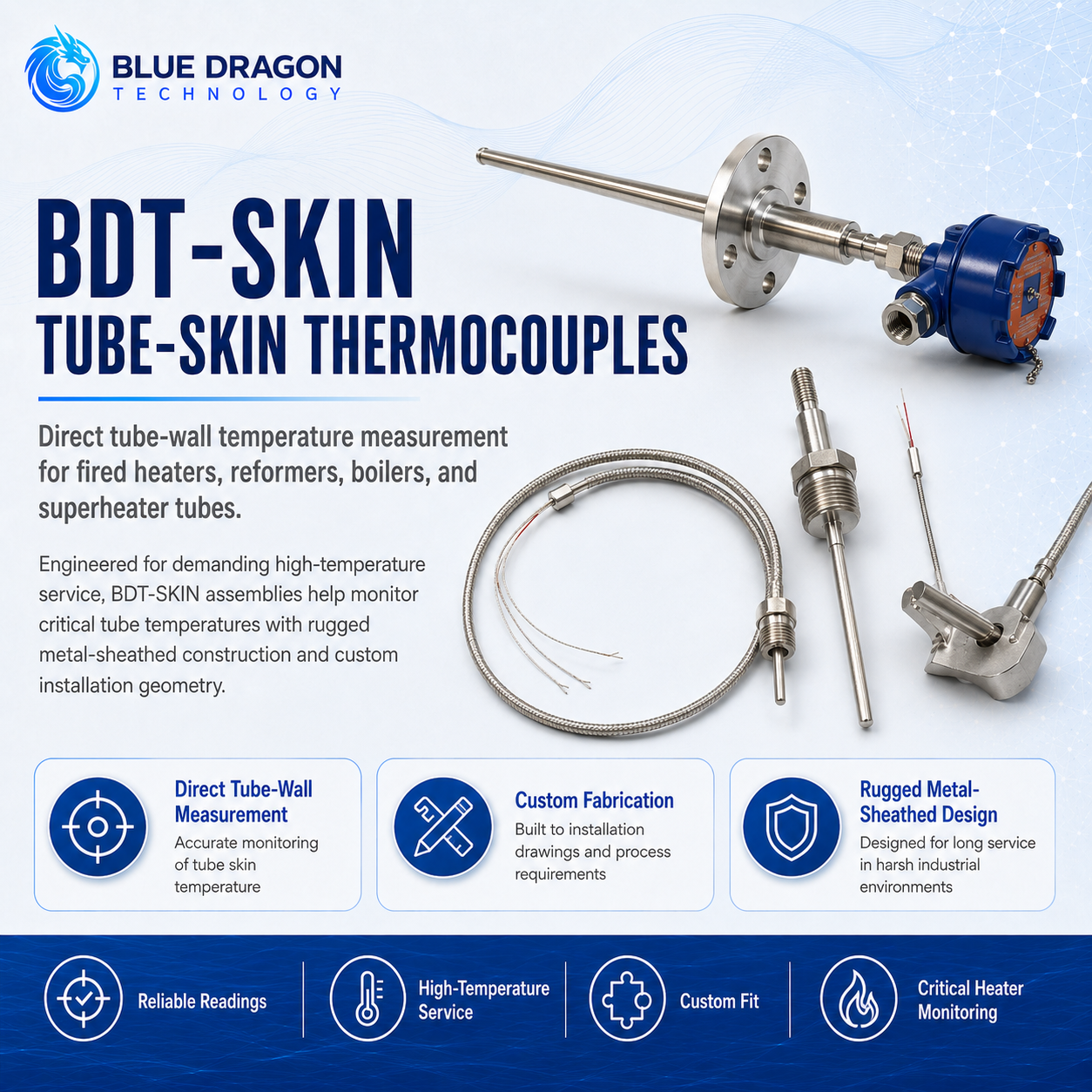
The BDT-SKIN is an engineered tube-skin thermocouple assembly for direct measurement of external tube-wall temperature in petrochemical heaters, boiler and superheater tubes, reformers, cracking furnaces, and other high-temperature process equipment.

MESIT configurations use a metal sheath with MgO-insulated thermocouple wire and may incorporate a curved heat-retention shield, expansion loops or coils, and weldable mounting clamps. Each assembly is fabricated from the installation drawings so that the sensing junction, mounting arrangement, routing, length, and termination suit the tube geometry and operating conditions.

Distinctive Capabilities

  • Expansion loops or coils to accommodate thermal movement
  • Weldable mounting clamps for secure installation
  • Custom fabrication from installation drawings
  • Application-specific sensor routing, length, and termination
Performance & Technical Data

The measurement method and the values that matter.

How it measures

Measurement Principle

Two dissimilar thermocouple conductors generate a thermoelectric voltage in response to the temperature difference between the measuring junction and the reference junction. In the BDT-SKIN assembly, the measuring junction is thermally coupled to the external tube surface so that the resulting signal represents the local tube-wall temperature. The mounting arrangement, heat-retention shield, surface contact, sheath routing, and expansion allowance are engineered to support representative measurement while accommodating tube movement and the surrounding thermal environment.

Measurement ParametersExternal tube-wall or equipment-surface temperature
Sensor technologyThermocouple; type selected for the application
ConstructionMetal sheath with MgO-insulated thermocouple wire
Documented sensor lengthFrom a few feet to over 50 ft; final length is project specific
Surface interfaceEngineered measuring junction with curved heat-retention shield
Thermal-growth compensationExpansion loop or coil where required

Complete Technical Data

Mounting
Weldable clamp or project-specific attachment arrangement
Tube size and geometry
Designed from installation drawings
Sheath, shield, and mounting materials
Selected for the operating temperature and service environment
Temperature range
Dependent on thermocouple type, construction materials, mounting, and service conditions
Termination
Project-specific cable, connector, terminal head, or junction-box arrangement
Calibration and documentation
Specified according to project requirements
Availability
Available for project application review and quotation
Industrial Use

Applications and industries.

Typical Applications

Petrochemical process-heater tube-wall temperature measurementBoiler and superheater tube monitoringFired-heater and process-furnace tubesSteam-reformer and cracking-furnace tubesHigh-temperature piping and equipment surfacesThermal-condition monitoring of process tubesTube-Skin Temperature Measurement

Industries Served

Chemical ProcessingCoal & Coal ChemicalFertilizers & ChemicalsHydrogen & SyngasPetrochemicalsPower GenerationRefining
Engineering & Integration

Built for specification, installation, and long-term operation.

Engineering focuses on the thermal contact, attachment method, heat shielding, expansion accommodation, sensor routing, and termination required to obtain representative tube-wall measurements without overstressing the assembly.

Measurement targetExternal tube wall or equipment surface
Attachment basisCustom weldable clamp or project-specific mounting
Thermal movementExpansion loop or coil where required
Engineering inputTube geometry, operating conditions, routing, and installation drawings

Sensor Construction

  • Project EngineeredThermocouple type, measuring-junction construction, sheath, heat shield, mounting arrangement, expansion loop, lead length, and termination are selected for the application.
  • Project EngineeredThe sensor assembly is fabricated against the tube geometry and approved installation drawings.
  • Application DependentTerminal heads, junction boxes, extension cables, connectors, and signal-conditioning arrangements are defined during project review.

Materials & Junction Design

  • StandardThe thermocouple measuring junction is thermally coupled to the external tube or equipment surface.
  • Project EngineeredThe contact geometry, heat-retention shield, clamp, weld attachment, and sheath route are designed around the monitored tube.
  • Application DependentSurface preparation, attachment procedure, and local thermal conditions must be reviewed before fabrication and installation.

Mounting & Installation

  • Project EngineeredInstallation is based on the tube diameter, tube material, furnace or boiler geometry, available access, expected thermal movement, and cable-routing requirements.
  • Project EngineeredExpansion loops or coils are positioned to accommodate movement without transferring excessive mechanical stress to the sensing junction.
  • Application DependentWelding and mounting procedures must follow the plant-approved installation and material-control requirements.
  • StandardA passive thermocouple does not require local operating power; any transmitter or signal conditioner has separate project-specific utility requirements.

Signal & Termination

  • Application DependentThe thermocouple signal may be connected through compatible extension cable to a temperature transmitter, control system input, monitoring system, or project-specific junction box.
  • Project EngineeredThermocouple type, polarity, extension-cable type, cold-junction compensation, channel identification, and termination details must be coordinated with the plant instrumentation system.
  • Application DependentTransmitter outputs, communication protocols, alarms, and control-system integration are specified separately when required.

Calibration & Quality

  • Application DependentThermocouple type, tolerance class, measuring-junction construction, and required calibration documentation are specified at quotation.
  • Project EngineeredCalibration points and traceability requirements should reflect the intended operating range and plant quality system.
  • StandardSensor identification and polarity must remain traceable through fabrication, installation, and termination.

Maintenance & Replacement

  • StandardPeriodic inspection should verify the mounting condition, surface contact, sheath integrity, expansion-loop condition, cable routing, and terminal connections.
  • Application DependentInspection intervals are determined by the operating temperature, thermal cycling, vibration, furnace environment, and plant maintenance strategy.
  • Project EngineeredReplacement assemblies should preserve the approved sensor position, attachment geometry, thermocouple type, and routing arrangement.

Process & Application Considerations

  • Application DependentWelding or attachment to process tubes must be performed only under approved plant procedures and material-control requirements.
  • Application DependentTube material, operating temperature, thermal expansion, vibration, radiant heat, and furnace atmosphere must be included in the application review.
  • Project EngineeredHazardous-area accessories or electrical equipment require the appropriate project-specific certification.
  • StandardThe sensor assembly must not obstruct required inspection access or impose unacceptable mechanical loading on the monitored tube.
Application Review

Application Engineering Notes

Application-specific construction

Each tube-skin thermocouple is configured for the furnace or boiler, monitored tube, temperature duty, mounting method, and site requirements. Thermocouple type, range, tolerance, response, sheath material, dimensions, hazardous-area provisions, and calibration are selected for the project rather than supplied as one universal combination.

Configuration information

Selection requires the tube outside diameter and material, normal and maximum wall temperatures, furnace or boiler arrangement, thermocouple preference, mounting method, thermal-expansion direction, sheath route, lead length, termination location, hazardous-area classification, and documentation requirements. Final technical values are confirmed for the selected construction.

Project Delivery

Project Integration & Support Scope

Blue Dragon reviews the measurement objective, interfaces, documentation, commissioning, and lifecycle requirements as part of project configuration. The scope below identifies the principal items to confirm before order placement.

Measurement Objective
Direct tube-wall or equipment-surface temperature measurement for fired heaters, boilers, superheaters, reformers, cracking furnaces, and other demanding high-temperature equipment.
Signal Outputs
The passive thermocouple provides a millivolt signal through the selected extension cable and termination. A transmitter, conditioned output, local indication, or communication protocol is supplied only when specified.
Data Integration
The thermocouple can connect to a compatible transmitter, DCS or PLC temperature input, monitoring system, or project-specific junction box. Thermocouple type, polarity, cold-junction compensation, channel identification, grounding, shielding, and termination must match the plant system.
Alarms & Diagnostics
High-temperature alarms, sensor-failure detection, open-circuit handling, shutdown logic, and communication status are normally provided by the connected transmitter or plant control system, not by the passive sensor assembly.
Documentation
The project package may include approved installation drawings, sensor and tag schedule, thermocouple and material details, cable and termination information, welding or mounting requirements, calibration certificates, inspection records, and project-specific quality documents.
Commissioning Support
Commissioning can include drawing and tag verification, mounting and surface-contact inspection, expansion-loop and routing review, polarity and continuity checks, loop testing, transmitter or DCS channel verification, and handover documentation.
Lifecycle Support
Lifecycle support covers mounting and surface-contact inspection, sheath and cable condition, expansion-loop integrity, terminal checks, calibration guidance, replacement assemblies, troubleshooting, spare parts, and long-term technical assistance.

Application Engineering

Discuss your measurement application.

Share the sample, measurement range, operating conditions, project location, and timeline. Blue Dragon Technology will review the application and recommend the appropriate configuration.