Available Available for project-specific extreme-temperature application review and quotation
Blue Dragon BDT Flow Measurement Series
FF1225-XT

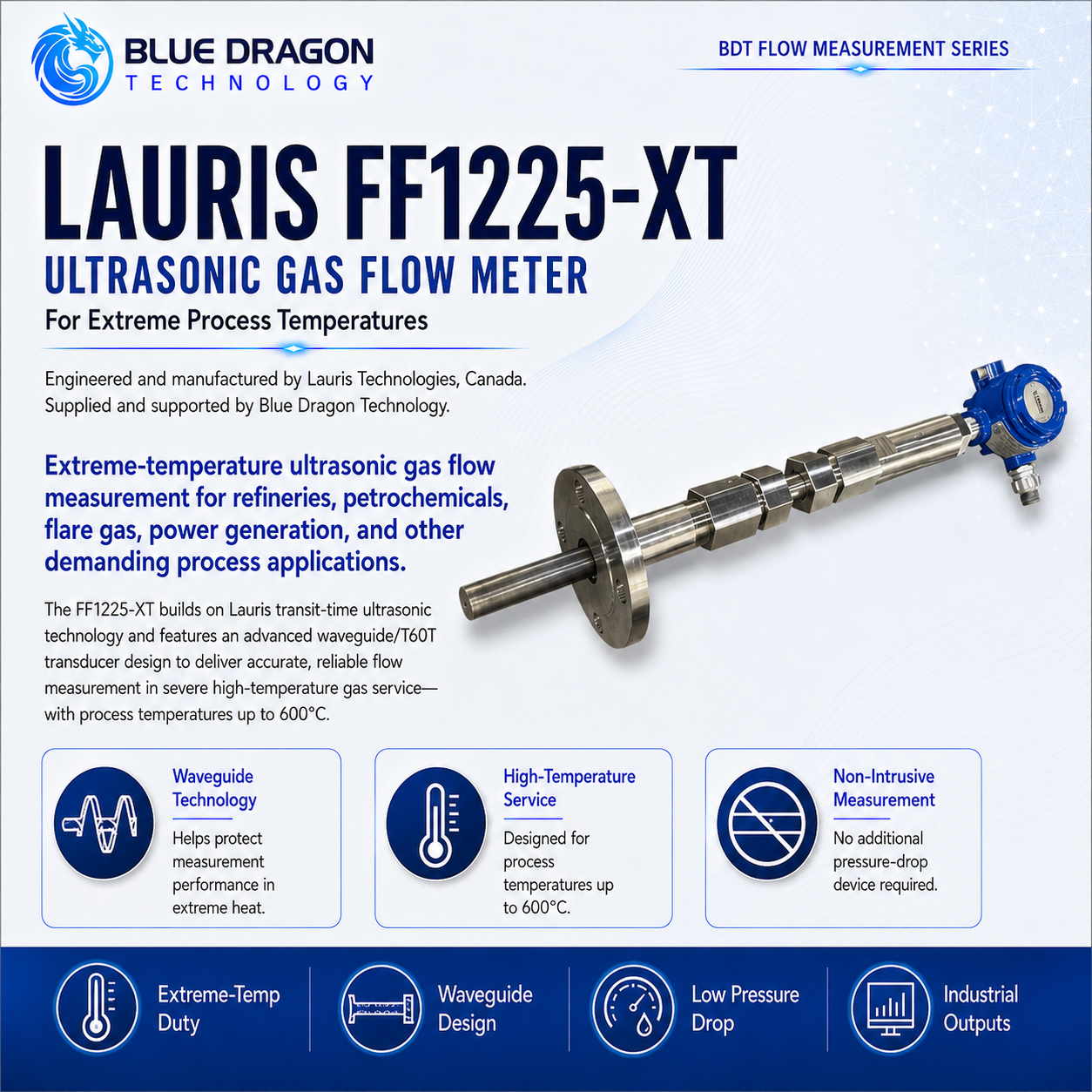
Lauris FF1225-XT Extreme-Temperature Ultrasonic Gas Flow Meter

Waveguide ultrasonic gas-flow measurement for extreme process temperatures from −253°C to +600°C.

Brand: Lauris Technologies Manufactured by: Lauris Technologies, Canada Supply & support: Blue Dragon Technology
Product Overview

Purpose-built measurement, clearly presented.

The Lauris FF1225-XT extends the FF1225 transit-time platform to extreme process temperatures from −253°C to +600°C. Its waveguide construction separates the sensitive transducer elements from the most severe thermal zone while retaining direct ultrasonic measurement of the process gas.

The meter is configured for the required pipe diameter, pressure, temperature, gas composition, process connection, electronics location and hazardous-area classification. The current Lauris cutsheet covers pipe diameters from 4 to 80 inches, gas velocities from 0.01 to 100 m/s and process pressure from 0.5 to 100 bar absolute.

Distinctive Capabilities

  • Waveguide-based isolation of sensitive transducer elements
  • Minimum detectable gas velocity down to 0.01 m/s
  • Maximum gas velocity up to 100 m/s
  • Cryogenic gas and hydrogen-related capability
  • High-temperature flare, flue-gas and combustion applications
  • No moving primary measurement components
Performance & Technical Data

The measurement method and the values that matter.

How it measures

Measurement Principle

Ultrasonic pulses are transmitted with and against the gas flow along an axial acoustic path. The difference between the upstream and downstream transit times is used to calculate gas velocity and volumetric flow. In the FF1225-XT, acoustic waveguides transmit the signal between the process and transducer elements located away from the extreme-temperature zone. This protects the sensitive elements from prolonged direct exposure while retaining the axial transit-time measurement principle.

Repeatability0.2%
Meter typeExtreme-temperature waveguide ultrasonic gas flow meter
Operating principleUltrasonic transit-time measurement using waveguide technology
Acoustic pathsFF1225 single-path base configuration; other path counts require Lauris confirmation
Published process-temperature range-253°C to +600°C
Velocity range0.01 to 100 m/s

Complete Technical Data

Published accuracy
1.0% to 2.5%; final performance is configuration and application dependent
Published turndown ratio
6,000:1
Waveguide length
18 in (0.4 m)
Pipe diameter
4 to 80 in
Process pressure
0.5 to 100 bar absolute
Primary waveguide material
Titanium
Process connection
ANSI Class 150 raised-face flange, 2 in or 3 in
Power Supply
24 VDC or 100 to 250 VAC
Power consumption
2.5 W maximum
Communications & Outputs
4–20 mA, Modbus and HART
LCD display
Standard; may be omitted for low-temperature operation
Transmitter enclosure
Die-cast aluminum or stainless steel
Hazardous-area approvals
CSA or UL Class I, Division 1, Groups B, C and D, T4; ATEX Zone 1; IECEx Zone 1, subject to ordered configuration
Sunshade
GRP or stainless-steel sunshade available
Availability
Available for project-specific application review and quotation
Development noticeExtreme-temperature limits, pressure rating, materials, accuracy and approvals are configuration dependent and require application review.
Industrial Use

Applications and industries.

Typical Applications

High-temperature process-gas measurementFurnace and combustion-exhaust measurementBoiler and flue-gas flowHigh-temperature flare and vent gasRefinery and petrochemical furnace applicationsSteel, metallurgy and heat-treatment processesCement, glass and ceramic kiln exhaustThermal-oxidizer and incinerator gasCryogenic gas measurementLiquid-hydrogen and hydrogen-related test or process applications subject to configurationExtreme-temperature research and pilot plants

Industries Served

Boilers & Steam SystemsCement, Glass & CeramicsChemical ProcessingCombustion & Flue GasFired Heaters & Process FurnacesFlare, Vent & Associated GasHydrogen & SyngasIndustrial Furnaces & Heat TreatmentNatural Gas & LNGPetrochemicalPower GenerationRefineriesSteel & Metallurgy
Engineering & Integration

Built for specification, installation, and long-term operation.

Each FF1225-XT application requires thermal, mechanical and acoustic engineering of the waveguide transducers, process materials, meter body, insulation, electronics location, pressure boundary and installation arrangement.

Published temperature range−253°C to +600°C
Measurement architectureTransit-time ultrasonic measurement with waveguide technology
Published velocity range0.01 to 100 m/s
Configuration basisTemperature profile, pressure, gas, pipe and required accuracy

Meter Configuration

  • StandardFF1225 ultrasonic flow-processing electronics combined with an extreme-temperature inline acoustic arrangement.
  • Project EngineeredWaveguide length, transducer location, process-wetted materials, meter-body material, flange class, spool dimensions, insulation clearances and electronics mounting.
  • Application DependentCryogenic and high-temperature configurations may require different materials, seals, thermal barriers, supports and installation practices.
  • OptionalPressure and temperature transmitters, remote electronics, alternative outputs and project-specific hazardous-area configurations.
  • Project Engineeredwaveguide length; process-temperature range; pipe diameter; process connection; pressure class; process and waveguide materials; single- or alternative path arrangement subject to Lauris approval; local or remote electronics; outputs; display; enclosure; sunshade; hazardous-area approvals; calibration and thermal-verification package.

Transducer & Pipe Interface

  • StandardDirect measurement of gas within the process pipe without extracting or conditioning a sample.
  • Project EngineeredThe waveguide interface transfers acoustic energy between the gas stream and transducer elements positioned outside the most extreme thermal zone.
  • Application DependentGas composition, pressure, temperature gradient, condensation, solids, thermal cycling and acoustic attenuation must be evaluated.

Installation Geometry & Utilities

  • Project EngineeredConfirm pipe orientation, thermal expansion, insulation thickness, support loads, flange temperature, accessible transducer location and allowable electronics temperature.
  • Application DependentHigh-temperature installations may require extended standoffs, insulation penetrations, heat shielding or remote electronics.
  • Application DependentCryogenic installations require material, contraction, sealing, condensation and ice-management review.
  • StandardThe transmitter power and output architecture are selected from the applicable FF1225 platform options.

Communications & Integration

  • Application DependentAnalogue and digital outputs, pressure and temperature inputs, totalizer settings and communication protocols are selected from the FF1225 electronics platform.
  • Project EngineeredStandard-flow calculations must use the correct pressure, temperature, compressibility and reference-condition basis.
  • Project EngineeredControl-system logic should include high or low process-temperature alarms, acoustic-signal diagnostics and status handling for pressure or temperature input failure.

Verification & Calibration

  • Project EngineeredCalibration and verification must cover the required velocity range and consider the extreme-temperature application conditions.
  • Application DependentThe complete temperature range may not be reproduced during conventional flow calibration; the proposed calibration and thermal-verification method must therefore be agreed with Lauris.
  • StandardMaterial traceability, transducer identification, waveguide dimensions, pressure-boundary records and transmitter configuration should be included in the project quality package.
  • Project EngineeredCritical applications may require dimensional inspection, pressure testing, material certification, thermal testing and documented signal-performance verification.

Maintenance & Service

  • StandardPeriodically inspect waveguides, transducer connections, seals, insulation interfaces, cables, supports and transmitter diagnostics.
  • Application DependentThermal cycling can affect joints, supports, seals and alignment and should be considered when defining inspection intervals.
  • Project EngineeredTransducers and electronics should be positioned for safe inspection without unnecessary disturbance of high-temperature or cryogenic insulation.
  • Application DependentShutdown and cool-down or warm-up requirements must be defined before intrusive maintenance.

Application Limits & Environmental Rating

  • Project EngineeredMaterials, flanges, seals, pressure rating and supports must be suitable for the full design-temperature range.
  • Application DependentPersonnel protection, insulation, burn hazards, cryogenic hazards, thermal expansion and contraction must be addressed by the plant design.
  • Application DependentHydrogen, oxygen-enriched gas, corrosive gas or flammable gas service requires a dedicated compatibility and hazardous-area review.
  • StandardNo universal pressure, hazardous-area or certification claim should be applied to every FF1225-XT configuration.
Application Review

Application Engineering Notes

Provide the complete operating and design temperature profile rather than only one maximum temperature. Include startup, shutdown, upset, steam-out, regeneration, purging and ambient conditions.

Also provide pipe size, schedule, pressure, gas composition, velocity and flow range, moisture or solids loading, insulation details, flange requirements, available transducer clearance, electronics location, hazardous-area classification and the required calibration or testing documentation.

Final suitability is confirmed for the specific process temperature profile, waveguide arrangement, construction materials, pressure boundary, insulation, electronics location, and transmitter configuration.

Application Engineering

Discuss your measurement application.

Share the sample, measurement range, operating conditions, project location, and timeline. Blue Dragon Technology will review the application and recommend the appropriate configuration.