Available Available for application review and quotation
Sulfur Analysis Series
Model 800TS

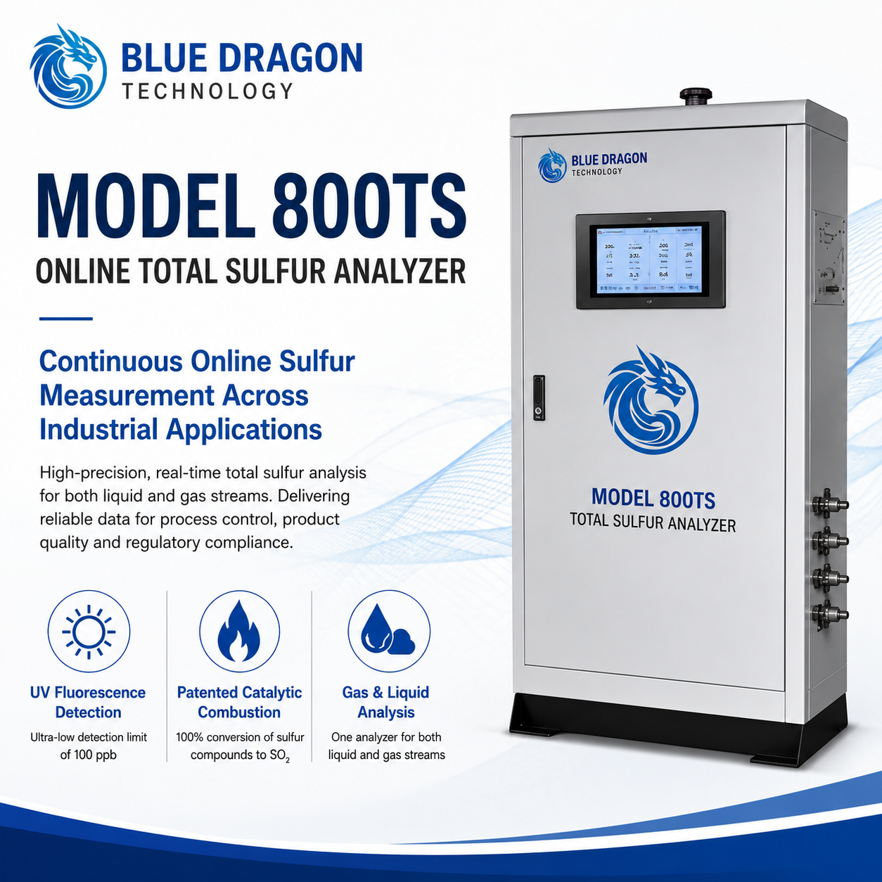
Model 800TS Online Total Sulfur Analyzer

Continuous online total sulfur analysis using high-temperature catalytic combustion and ultraviolet fluorescence detection.

Brand: Blue Dragon Technology Supply & support: Blue Dragon Technology
Product Overview

Purpose-built measurement, clearly presented.

The Model 800TS is an industrial online total sulfur analyzer for continuous process and product-quality monitoring. The documented standard liquid configuration is designed for light hydrocarbon samples such as gasoline, diesel, naphtha, and related petroleum fractions.

Automatic task scheduling, external-standard calibration, per-stream outputs, diagnostics, and optional multi-stream switching support unattended operation. Gas-phase use and the final sample-handling arrangement must be confirmed for the ordered application.

Distinctive Capabilities

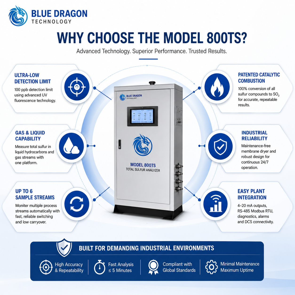
  • Automatic task scheduling with single-stream or optional multi-stream operation
  • Catalytic conversion and membrane drying for robust light-hydrocarbon analysis
  • External-standard calibration with per-stream analogue reporting
  • Real-time concentration, operating status, alarms, and fault diagnostics
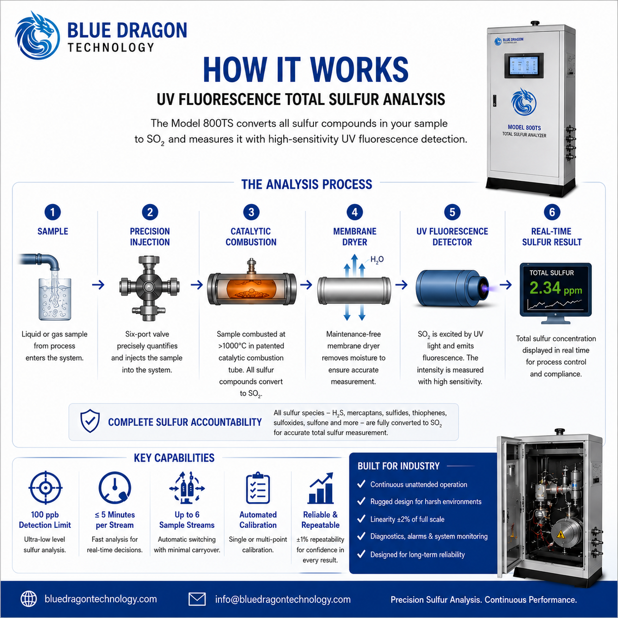
D01 Complete Measurement ProcessRepresentative sample delivery, quantitative injection, catalytic combustion, UV fluorescence detection, signal processing, and the reported total sulfur result.
Performance & Technical Data

The measurement method and the values that matter.

How it measures

Measurement Principle

A quantitative six-port valve introduces the sample into a catalyst-filled combustion tube maintained above 1000 °C. Sulfur compounds are oxidized to sulfur dioxide, combustion moisture is removed by a membrane dryer, and the sulfur dioxide is measured by ultraviolet fluorescence. The integrated signal is proportional to total sulfur concentration.

Measurement Range0–100 ppm, customizable
Detection Limit100 ppb under specified conditions
Repeatability±1% of full scale
Analysis Time≤5 minutes on the same sample stream
Measurement ParametersTotal sulfur
D02 UV Fluorescence Detection PrincipleOptical excitation, filtration, fluorescence measurement, signal processing, and conversion of the detector response into total sulfur concentration.

Complete Technical Data

Standard documented sample configuration
Liquid light hydrocarbons; gas applications require confirmed project configuration
Measurement Principle
High-temperature catalytic combustion with ultraviolet fluorescence detection
Published measurement range
0–100 ppm (w/w); other ranges available by application review
Linearity
±2% of full scale
Stream capacity
1 to 6 automatic streams, configuration dependent
Calibration
External standard; single-point or multi-point
Analogue output
4–20 mA per configured stream
Digital communication
RS-485, Modbus RTU
Referenced methods
ASTM D5453, ASTM D6667, ISO 20846, GB/T 34100, and SH/T 0689
Ambient temperature
0–40 °C
Power Supply
220 VAC ±10%, 50/60 Hz; manual rating 1500 W
Dimensions
705 × 386 × 1155 mm
Weight
Approximately 100 kg
Availability
Available
Safety & Compliance

Hazardous-Area / Explosion Protection

Certification, protection concept, and marking information for the applicable configured instrument.

Explosion Protection
Ex eb ia mb pxb IIC T4 Gb
PCEC Certification
Certified hazardous-area / explosion-protection configuration
European Standards Verification
Independently verified by ECM against applicable EN 60079 standards related to Directive 2014/34/EU (ATEX).
Environmental Rating
IP65; Ta -20 °C to +60 °C
Industrial Use

Applications and industries.

Typical Applications

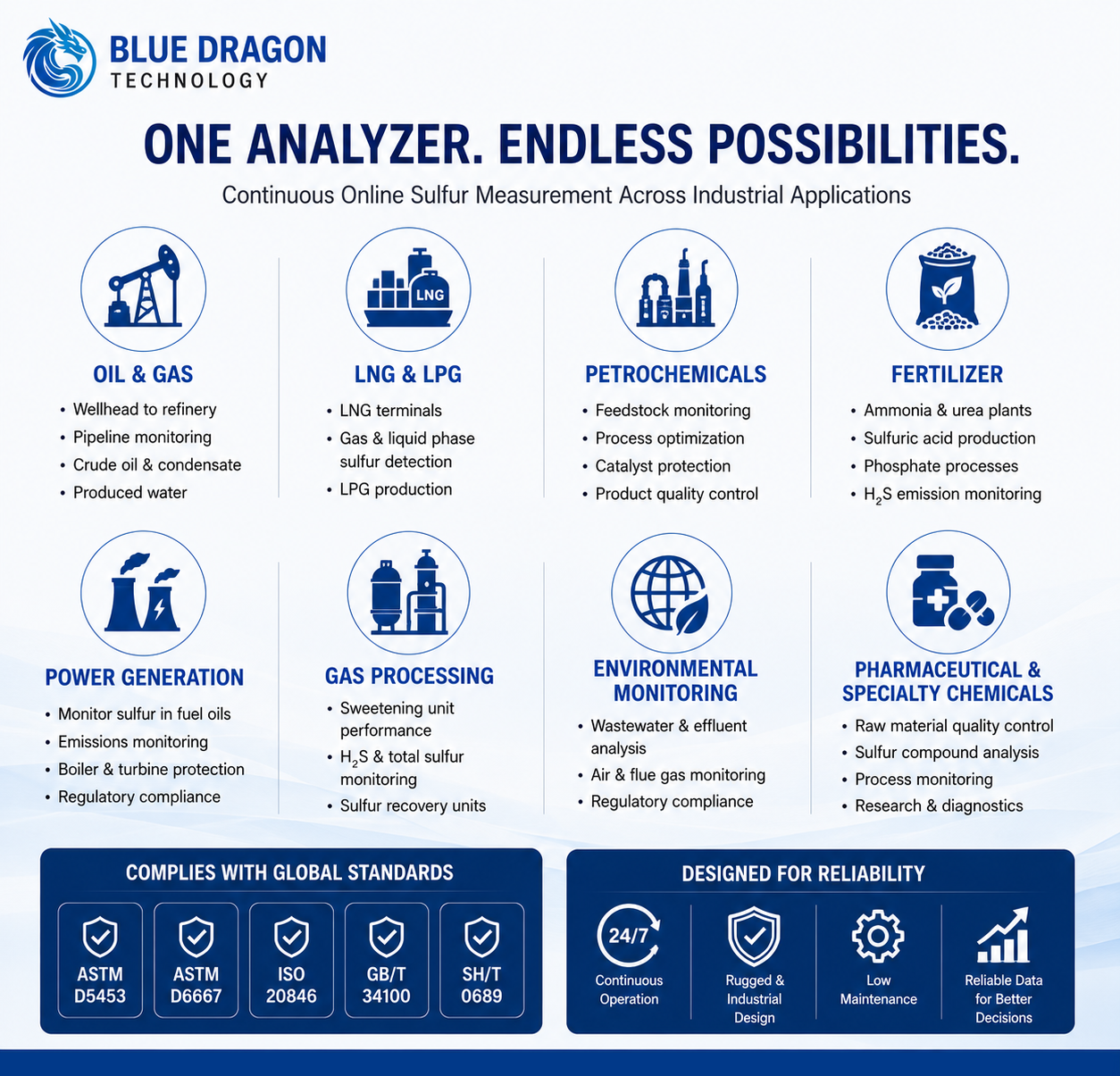
Gasoline, diesel, naphtha, kerosene, and gas-oil sulfur monitoringRefinery process control, blending, and final-product quality verificationPetrochemical feedstock and product monitoringLPG, natural-gas, or other gas-phase applications with confirmed project configurationFuel terminal, storage, and transfer quality monitoringOnline Total Sulfur MeasurementTotal Sulfur in Liquid Hydrocarbon Streams

Industries Served

Biofuels & Renewable FuelsChemical ProcessingEnvironmental Monitoring & ComplianceFertilizers & ChemicalsNatural Gas & LNGOil & GasPetrochemicalsPipelines & MidstreamPower GenerationRefining
Engineering & Integration

Built for specification, installation, and long-term operation.

Practical requirements for configuring the analyzer, conditioning the sample, providing utilities, integrating plant signals, and maintaining reliable online sulfur measurement.

Sample architectureQuantitative six-port injection with application-specific pretreatment
Stream capacityOne to six automatic sample streams
Plant integration4–20 mA per stream and RS-485 Modbus RTU
Installation basisStable analyzer environment with engineered sample, vent, gas, and purge services
D03 Multi-Stream and Sample-Handling ArchitectureProcess streams, project-engineered conditioning, stream selection, calibration routing, analyzer measurement, and plant reporting interfaces.

System Configuration

The base analyzer contains the injection, catalytic reaction, membrane-drying, UV fluorescence detection, control, and workstation functions required for total sulfur analysis.

  • StandardMain analyzer with quantitative injection, combustion furnace, catalyst tube, membrane dryer, UV fluorescence detector, control system, and workstation software
  • OptionalAnalyzer Sample System — supplied only when ordered and engineered for the process stream
  • OptionalAnalyzer House — supplied only when ordered and engineered for the installation
  • OptionalAnalyzer Recycling System — supplied only when ordered and engineered for sample return or recovery
  • Application DependentNumber of streams, range, gas-phase configuration, and hazardous-area arrangement
  • OptionalAnalyzer Sample System — project-engineered sample conditioning, filtration, pressure regulation, stream selection, calibration routing, and fast-loop components; not included with the base analyzer unless ordered

Sample Handling

Stable sulfur results depend on clean, pressure-controlled, representative sample delivery.

  • Project EngineeredPretreatment may include stream-selection valves, self-cleaning filtration, pressure indication, pneumatic shut-off valves, flowmeters, needle valves, fast loops, a calibration path, and a grab-sampling point
  • StandardThe six-port valve uses a quantitative loop for repeatable sample introduction
  • StandardSample and standard-sample paths can be switched without rebuilding the analyzer piping
  • Application DependentSample lines should be short, clean, dry, compatible with the sample, and free from entrained material that can block the system
  • Application DependentHigh-viscosity, corrosive, explosive, fluoride-, phosphorus-, or heavy-metal-containing samples require rejection or specialist review
  • Integrated filters, flow meters, and fast-loop sample handling help maintain consistent analysis conditions.

Installation & Utilities

The analyzer requires a stable installation close to the sampling point, with correctly designed gas, sample, vent, waste, electrical, and purge services.

  • Standard220 VAC ±10%, 50/60 Hz with protective grounding and correctly rated isolation
  • StandardZero air for carrier and combustion-support gas, normally 0.2–0.3 MPa and at least 1.5 L/min
  • StandardPneumatic drive gas normally at least 0.4 MPa; calibration-gas pressure typically 0.1–0.2 MPa
  • Application DependentInstrument or purge air capacity and final pressure are governed by the positive-pressure system and project drawing
  • StandardUse suitable 316L stainless-steel tubing for site sample and gas lines
  • StandardVent and waste lines must remain short, unrestricted, and free from backpressure

Integration & Communications

The control system supports local operation, scheduled analysis, result storage, diagnostics, and plant data transfer.

  • StandardOne 4–20 mA output for each configured stream
  • StandardLocal real-time concentration, component status, and fault information
  • StandardAlarm functions include furnace temperature, pressure, gas-flow, and detector or system conditions
  • StandardFault handling can stop sample flow and manage furnace shutdown or cooling

Calibration & Quality Control

Calibration uses external liquid standards and should be performed only after temperatures, gas flows, pressure, and the analytical baseline are stable.

  • StandardA dedicated standard-sample path supports calibration without dismantling process piping
  • StandardPer-stream 4–20 mA output scaling and verification
  • StandardRoutine comparison with a representative grab sample can support online-result verification
  • Application DependentStandard concentration, calibration frequency, and range must match the actual sample and operating range
  • View product sheet, brochure, manual, and quality control documents.
  • Review detailed product information, operating documentation, and quality control materials for the Blue Dragon Technology Model 800TS Online Total Sulfur Analyzer.

Maintenance & Service

Preventive maintenance focuses on leak integrity, clean sample delivery, the injection path, combustion components, gas flows, and detector stability.

  • StandardInspect the analyzer, gas pressures, sample flow, tubing, and leakage condition routinely
  • StandardClean or replace the pretreatment filter screen according to sample cleanliness
  • StandardInspect the catalytic combustion tube and replace it when performance or condition requires
  • StandardPerform periodic calibration or standardization after service and at the site-defined interval
  • StandardAllow the furnace and reaction components to cool fully before internal maintenance
  • Application DependentRecommended spare parts include filters, seals, injection components, catalyst tube, membrane dryer, and valve items

Safety & Application Considerations

High temperature, mains voltage, pressurized gases, hydrocarbon samples, and classified-area installation require trained personnel and site-approved procedures.

  • StandardIsolate electrical power before opening the analyzer or servicing internal components
  • StandardTreat the combustion furnace and catalyst tube as hot after shutdown until verified cool
  • Application DependentThe standard manual primarily documents suitable liquid light-hydrocarbon samples
  • Project EngineeredClassified-area installation must follow the supplied Ex marking, certificate scope, analyzer nameplate, approved drawings, and site requirements
  • Application DependentGas-phase use, sample recovery, and analyzer-house design require application engineering
Application Review

Application & Configuration Review

System Scope

Optional · Project Engineered

The Analyzer Sample System, Analyzer House, and Analyzer Recycling System are supplied only when expressly included in the quotation and approved order documentation. They are not part of the base analyzer by default.

Sample Suitability

Application Review Required

The standard documented configuration is intended for light liquid hydrocarbons suitable for controlled vaporization and combustion. Gas-phase, highly viscous, corrosive, reactive, or otherwise unusual samples require written suitability review before use.

Configuration Control

Order Specific

Final utilities, hazardous-area protection, purge or pressurization, sample-system materials, stream count, calibration routing, vent or return arrangements, and installation scope are defined by the approved order-specific documentation and analyzer nameplate.

Document precedence

The supplied configuration and approved project documentation take precedence over general website information.

Project Delivery

Project Integration & Support Scope

Blue Dragon reviews the measurement objective, interfaces, documentation, commissioning, and lifecycle requirements as part of project configuration. The scope below identifies the principal items to confirm before order placement.

Measurement Objective
Continuous total sulfur measurement for light liquid hydrocarbons, process and product quality control, blending support, final-product verification, and approved gas-phase applications.
Signal Outputs
One 4-20 mA output is available for each configured stream. RS-485 Modbus RTU provides digital communication, while the local workstation displays concentration, operating status, alarms, and stored results.
Data Integration
Connect the analyzer to the plant DCS, PLC, SCADA, or historian through per-stream 4-20 mA signals and RS-485 Modbus RTU. Stream count, output scaling, register mapping, and integration ownership are confirmed in the project documents.
Alarms & Diagnostics
Local diagnostics cover furnace temperature, pressure, gas flow, detector condition, and other system faults. Configured fault handling can stop sample flow and manage furnace shutdown or cooling.
Documentation
The project package may include the product sheet, operating manual, approved datasheet, sample-system and utility drawings, I/O information, Modbus details, calibration records, and FAT or SAT documentation as ordered.
Commissioning Support
Commissioning can include utility verification, leak and flow checks, stream switching, external-standard calibration, 4-20 mA and Modbus checks, alarm testing, and comparison with a representative grab sample.
Lifecycle Support
Lifecycle support covers calibration, troubleshooting, filters, seals, injection components, catalyst tube, membrane dryer, valve items, consumables, repairs, and long-term technical assistance.
D04 Installation Boundary, Utilities and Plant IntegrationProcess-side responsibilities, optional project equipment, the base analyzer boundary, plant-provided utilities, and DCS, PLC, or SCADA integration.
Online Analyzer Configuration

Sample System & Online Analyzer Readiness

Reliable online measurement depends on the process interface as well as the analyzer. Confirm the following application data before final configuration and quotation.

Sample Type & Phase
The documented standard configuration is for liquid light hydrocarbons such as gasoline, diesel, naphtha, kerosene, and gas oil. LPG, natural gas, and other gas-phase samples require written application confirmation and an approved project configuration.
Measurement Range
Confirm the normal, minimum, and maximum sulfur concentration, required detection limit, alarm points, number of streams, and applicable method. The published standard range is 0-100 ppm by mass with a 100 ppb detection limit under specified conditions; other ranges require application review.
Sample Conditions
Provide sample pressure, temperature, phase stability, volatility, viscosity, water content, particulates, corrosive components, and expected matrix variation. Highly viscous, corrosive, explosive, fluoride-, phosphorus-, or heavy-metal-containing samples require specialist review.
Sample Handling
Define the take-off point, fast loop, stream selection, filtration, pressure and flow control, calibration path, grab-sample point, vent, waste, and return or recovery arrangement. Site sample lines should be short, clean, dry, compatible, and normally constructed from suitable 316L stainless-steel tubing.
Installation Area
Confirm indoor or outdoor location, analyzer shelter, ambient range, maintenance access, safe-area or hazardous-area requirements, positive-pressure arrangement, and distance from the sampling point. The analyzer requires a stable environment within the approved 0-40 degrees C ambient range.
Utilities
Standard requirements include 220 VAC plus or minus 10 percent, 50/60 Hz, protective grounding, zero air normally at 0.2-0.3 MPa and at least 1.5 L/min, pneumatic drive gas normally at least 0.4 MPa, calibration gas or standard supply, and unrestricted vent and waste lines. Purge-air requirements are project specific.
Response Requirement
Define whether the analyzer supports process control, blending, product release, compliance, alarm response, or trending. The published analysis time is no more than five minutes on the same sample stream; total response also depends on sample transport and stream switching.
Integration Requirement
Confirm the number and scaling of 4-20 mA outputs, RS-485 Modbus RTU settings, DCS or PLC tags, alarm handling, historian requirements, and responsibility for site wiring and signal mapping.
Commissioning Requirement
Verify sample suitability, utilities, leak integrity, gas pressures, sample flow, vent and waste routing, stream selection, calibration standards, output scaling, Modbus communication, alarms, task scheduling, and representative online-versus-laboratory comparison before handover.
Operational Visibility

Alarm & Diagnostic Matrix

A practical summary of process alarms, analyzer diagnostics, sample-system conditions, and plant-interface faults for the configured Model 800TS system.

Project Setpoint means the limit is selected for the ordered application. Recommended severity is generic website guidance; the site alarm philosophy is final.

High total sulfur

Process Severity: Critical
Trigger / Basis
Measured total sulfur reaches the configured high or high-high Project Setpoint for the active stream.
Instrument Response
The local result and analyzer status remain available; configured 4–20 mA and Modbus interfaces report the measurement and status.
Operator Response
Confirm the active stream and process condition, then verify the result by the approved grab-sample or laboratory procedure before quality action.
Reset & Ownership
The DCS or PLC owns process action. Setpoint, delay, latching, interlock, and reset follow the approved cause-and-effect.

Low total sulfur

Process Severity: Warning
Trigger / Basis
Measured total sulfur reaches a configured low Project Setpoint where a low limit is required.
Instrument Response
The analyzer continues reporting the measured value and available status through the configured interfaces.
Operator Response
Check stream identity, sample delivery, recent calibration, and process conditions before accepting the low result.
Reset & Ownership
Normally DCS or PLC owned. Alarm use, delay, latching, and reset are defined by the project alarm philosophy.

Result invalid or out of range

Measurement Quality Severity: Critical
Trigger / Basis
The result is outside the configured analytical range or the analyzer identifies the measurement as invalid.
Instrument Response
Fault or diagnostic status is presented locally and the affected result must not be treated as valid for control.
Operator Response
Place dependent control logic in its approved safe state, confirm range and sample condition, and investigate the active diagnostic.
Reset & Ownership
Analyzer status originates locally; bad-quality handling and reset ownership are defined in the DCS or PLC integration documents.

Furnace temperature deviation

Analyzer Severity: Critical
Trigger / Basis
Combustion-furnace temperature is outside the permitted operating band.
Instrument Response
The analyzer raises a temperature fault; configured fault handling can stop sample flow and manage furnace shutdown or cooling.
Operator Response
Stop relying on the measurement, isolate sample as required, allow safe cooling, and inspect the furnace, controller, and temperature circuit.
Reset & Ownership
Analyzer owned, with manual or automatic reset only after the documented safe recovery conditions are satisfied.

Carrier or combustion-gas condition

Utility Severity: Critical
Trigger / Basis
Monitored zero-air, carrier-gas, combustion-support flow, or pressure is below the required operating condition.
Instrument Response
The analyzer reports the gas-flow or pressure fault and may stop sample introduction under the configured fault sequence.
Operator Response
Check supply pressure, regulators, isolation valves, flow settings, tubing, leaks, and gas quality before restarting analysis.
Reset & Ownership
Analyzer or project utility logic owns detection. Reset only after stable gas conditions are restored.

Sample flow or pressure abnormal

Sample System Severity: Warning
Trigger / Basis
A monitored sample-flow or sample-pressure value leaves its Project Setpoint band.
Instrument Response
The analyzer or project sample-system PLC flags the condition; the affected stream result is treated as unavailable or suspect.
Operator Response
Verify the fast loop, filters, regulators, valves, tubing, vent or return path, and representative sample delivery.
Reset & Ownership
Ownership belongs to the analyzer sample system or DCS or PLC according to the approved piping and I/O design.

UV detector or optical-system fault

Analyzer Severity: Critical
Trigger / Basis
The UV fluorescence detector or associated optical and electronic system cannot provide a valid response.
Instrument Response
The analyzer displays fault information and the affected sulfur result is invalid.
Operator Response
Check the active diagnostic, stable utilities, baseline condition, detector connections, and authorized service requirements.
Reset & Ownership
Analyzer owned. Reset only after the detector condition is corrected and a valid check or calibration is completed.

Calibration validation failed

Quality Control Severity: Warning
Trigger / Basis
An external-standard calibration or validation does not meet the approved acceptance criterion.
Instrument Response
The attempted calibration is not accepted as a successful quality event and diagnostic status remains available.
Operator Response
Check standard identity and concentration, routing, injection, gas stability, contamination, method settings, and repeat the approved procedure.
Reset & Ownership
Quality-system owned. Release and reset require the approved acceptance rule and an authorized successful verification.

Stream-selection or sequence fault

Sample System Severity: Warning
Trigger / Basis
An optional multi-stream valve route or scheduled sequence does not reach the commanded state.
Instrument Response
The affected stream is not reported as a valid completed analysis and a fault or sequence status is presented.
Operator Response
Confirm valve actuation, pneumatic supply, stream assignment, line condition, calibration routing, and sequence configuration.
Reset & Ownership
Analyzer or sample-system PLC owned according to the ordered architecture; reset follows the validated sequence procedure.

Power or communication failure

Integration Severity: Critical
Trigger / Basis
Analyzer power is lost or the configured RS-485 Modbus link stops updating.
Instrument Response
The analyzer becomes unavailable on power loss; the receiving system detects missing, stale, or failed communication data.
Operator Response
Check safe power isolation, supply, protective devices, cable terminations, address, baud rate, and DCS or PLC communication health.
Reset & Ownership
The DCS or PLC owns stale-data and fail-safe action. Restart and communication recovery follow the approved commissioning procedure.
Product Media

See the instrument platform.

Product video and platform overview.

Technical Resources

Product Documents

Product Sheet first, followed by the Brochure, Manual, and any additional technical documents.

Application Engineering

Discuss your measurement application.

Share the sample, measurement range, operating conditions, project location, and timeline. Blue Dragon Technology will review the application and recommend the appropriate configuration.