

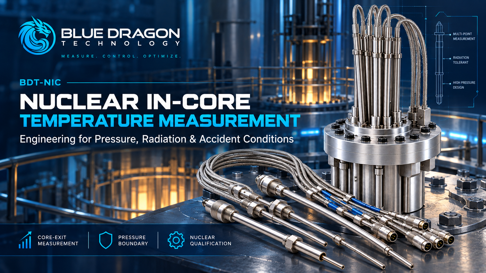
Core-Exit Temperature Measurement in Nuclear Reactors: Engineering Thermocouples for Pressure, Radiation and Accident Conditions
A thermocouple is one of the most established temperature-sensing technologies in industry. Its operating principle is straightforward: two dissimilar conductors generate a thermoelectric voltage related to the temperature difference between the measuring junction and the reference junction.
Inside or immediately above a nuclear reactor core, however, the measurement problem is no longer defined by the thermocouple alone. The sensing element may need to operate alongside reactor pressure, neutron and gamma radiation, mechanical loads, long cable runs, reactor-specific penetrations, safety-class requirements and plant instrumentation interfaces.
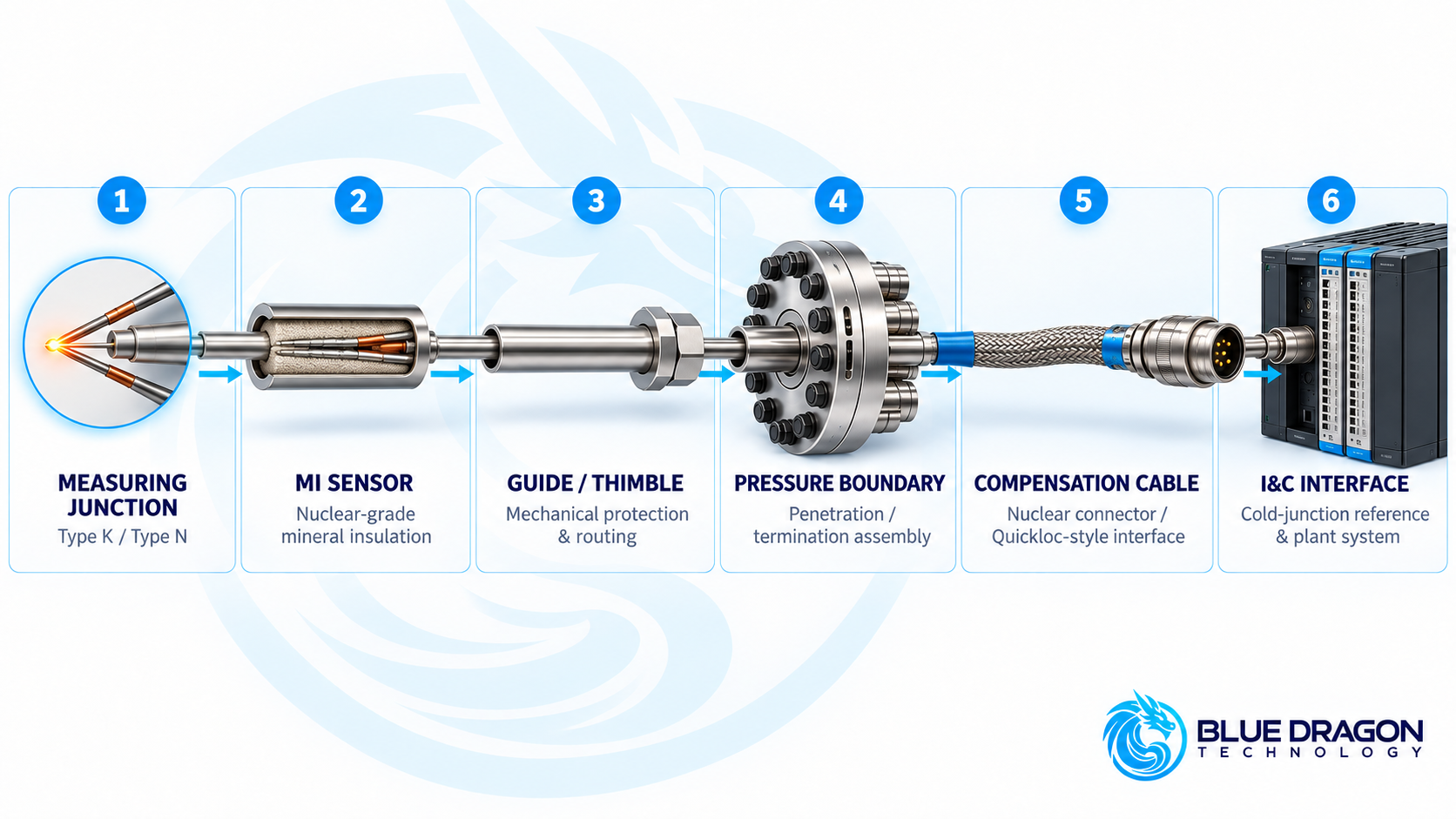
The relevant engineering object is therefore the complete temperature-measurement chain: from the measuring junction and mineral-insulated sensor through the guide, pressure boundary and compensation cable to the plant instrumentation and control system.
This article examines how nuclear core-exit and in-core temperature measurement systems are engineered around temperature capability, accuracy, response time, radiation environment, pressure containment, materials, service life and environmental qualification—and why these parameters must ultimately be defined for the specific reactor and measurement function. Blue Dragon addresses these project-specific applications through its BDT-NIC Nuclear In-Core Temperature Measurement Systems.
From Hot Junction to Plant I&C: The Complete Measurement Chain
A nuclear temperature measurement does not stop at the hot junction. The signal must travel through a mechanically and electrically controlled path before it becomes useful information inside the plant instrumentation system.
A representative measurement chain can include:
- Measuring junction — the thermoelectric sensing point
- Mineral-insulated thermocouple — providing compact, protected signal conductors inside a metallic sheath
- Guide or thimble — routing and mechanically protecting the sensing assembly
- Engineered pressure boundary — separating reactor/process pressure from the instrumentation side
- Compensation cable and termination — carrying the thermocouple signal beyond the penetration
- Plant I&C interface — including the appropriate cold-junction reference and measurement electronics
Mineral-Insulated Construction
Mineral-insulated, or MI, thermocouples place the thermoelement conductors inside a metallic sheath surrounded by compacted electrical insulation. This construction provides a small cross-section while mechanically protecting the conductors and maintaining electrical insulation along the sensor length.
For nuclear core-exit applications, Type K is an established reference thermocouple configuration, while Type N can be considered where required by the project. Depending on the design and qualification basis, sheath materials can include Inconel 600, 316 stainless steel or 304L stainless steel, with mineral insulation such as MgO or Al₂O₃.
Grounded and ungrounded junction arrangements can also be engineered according to the required electrical isolation, response and plant interface.
Temperature Capability Is Not the Same as Qualified Operating Range
One of the most important distinctions in nuclear temperature instrumentation is the difference between the temperature capability of the thermoelectric materials and the qualified operating range of the complete installed assembly.
For representative nuclear-grade Type K core-exit configurations, several different temperature ranges may be relevant:
- Typical PWR core-exit coolant environment: approximately 315–330 °C
- Typical specified measurement range: 0 to +400 °C, extendable according to calibration and configuration
- Representative post-accident / PAM indication: useful indication through approximately 650 °C for applicable configurations
- Type K thermoelement continuous capability: up to approximately 1,150 °C
- Type K short-term thermoelement capability: approximately 1,250 °C
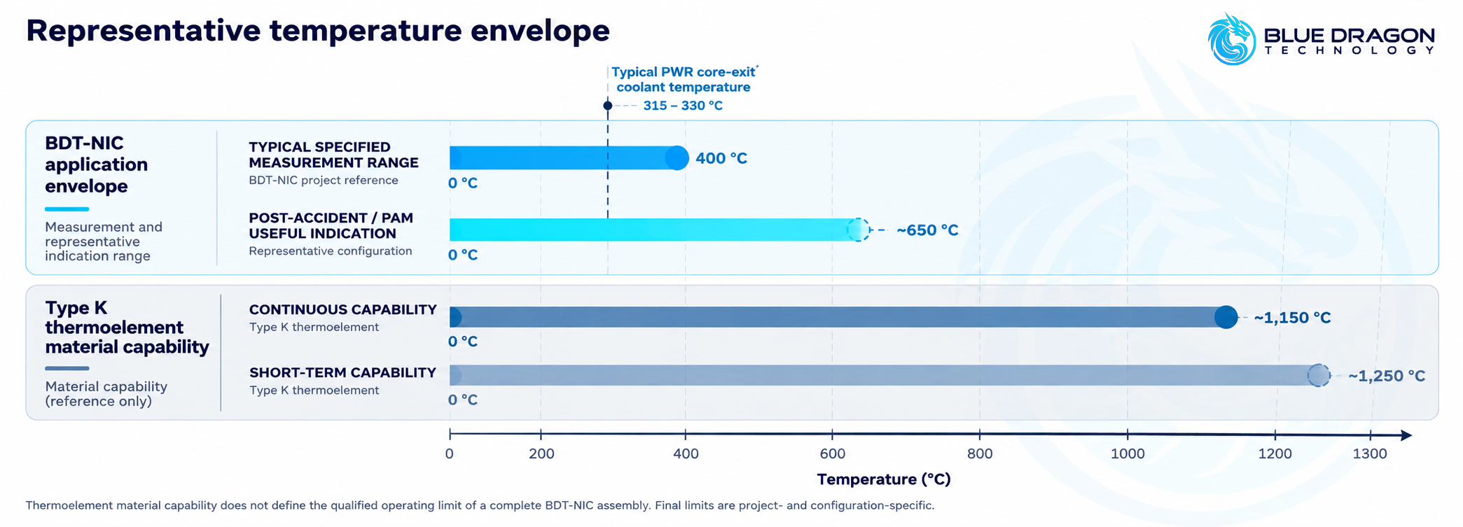
The thermoelement material may therefore tolerate a substantially higher temperature than the complete installed system is specified or qualified to measure.
The actual assembly limit depends on factors such as sheath alloy, sheath diameter, mineral insulation, mechanical geometry, pressure-boundary arrangement, cable and termination design, calibration and the required measurement mission.
Accuracy and Response Are System Properties
Reference Type K Performance
For a Type K Class 1 thermocouple, a representative reference tolerance is approximately ±1.5 °C to 375 °C, followed by approximately ±0.4% of reading over the applicable higher-temperature range.
The uncertainty of the complete installed chain is different from the tolerance of the thermocouple element alone. Around a representative PWR core-exit temperature of approximately 325 °C, a complete nuclear measurement chain may typically be around ±2 to ±2.5 °C, depending on the configuration.
Response Time Changes After Installation
A small-diameter mineral-insulated element can achieve a representative t50 response of approximately two seconds. Once that element is incorporated into an engineered reactor assembly, however, the surrounding finger, guide, sheath, mechanical protection and thermal coupling influence how quickly the final system responds.
Installed core-exit or IITA-type configurations may therefore respond over several seconds to tens of seconds, depending on the mechanical design.
This illustrates another recurring principle in nuclear instrumentation: performance must be evaluated at the system level, not simply from the properties of the bare sensing element.
Radiation Duty Depends on Where the Sensor Is Located
The term “in-core” can easily suggest that every sensor experiences the peak neutron environment inside the active core. In practice, radiation duty depends strongly on the actual measurement location.
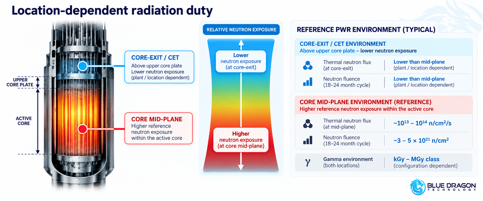
Core-exit thermocouples are positioned above the upper core plate rather than at the core mid-plane. Their neutron exposure is therefore different from the higher reference neutron environment within the active core, although gamma exposure remains a significant qualification consideration.
For context, representative PWR mid-plane conditions can be of the order of:
- Thermal neutron flux: approximately 1013–1014 n/cm²/s
- Thermal fluence per 18–24 month cycle: approximately 3–5 × 10²¹ n/cm²
- Core-exit neutron exposure: lower than the core mid-plane and dependent on plant and sensor location
- Gamma environment: potentially kGy–MGy class, depending on the configuration and location
Radiation Influences More Than Immediate Survivability
Long-term exposure can influence thermoelectric stability, measurement drift, insulation performance, sheath condition and other components within the measurement chain.
This is why a generic neutron-flux or gamma-dose number should not be treated as a universal thermocouple rating. The relevant radiation duty has to be established at the actual sensor location and assessed within the applicable plant environmental-qualification basis.
The Thermocouple Is Not the Reactor Pressure Boundary
Pressure is another area where the distinction between the sensor and the measurement system becomes important.
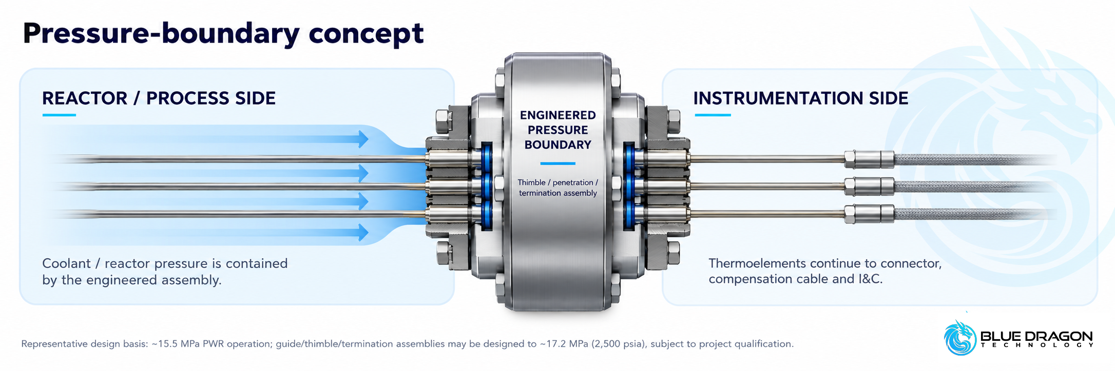
A large pressurized-water reactor can operate at reactor coolant system pressures around 15.5 MPa. Representative engineered IITA, guide or Quickloc-style pressure-boundary arrangements can be designed around approximately 17.2 MPa / 2,500 psia at 343 °C / 650 °F, subject to the actual project requirements.
The thermoelement itself is not the reactor coolant pressure boundary.
Pressure containment is provided by the engineered mechanical architecture around the sensing path, such as the thimble, guide, penetration, termination assembly and welded pressure-retaining components.
Pressure Integrity Becomes Part of Instrument Qualification
Depending on the design and purchase specification, pressure-boundary verification can include all-welded construction, hydrostatic pressure testing, helium leak testing, weld inspection and other integrity checks.
The result is not simply a thermocouple capable of sensing temperature. It is a temperature-measurement system engineered to coexist with the mechanical boundary of the reactor installation.
Mechanical Design Is Reactor-Specific
The sensing element itself may be only a few millimetres in diameter, while the complete measurement path can extend through reactor internals, the vessel head, penetrations and cable routing over substantial distances.
Representative nuclear MI configurations can include:
- MI sheath outside diameter: approximately 1.0–3.2 mm
- Compact combined configurations: commonly around 1.0–1.6 mm
- Overall length: engineered to the routing and potentially extending tens of metres
- Sheath materials: Inconel 600, 316 stainless steel or 304L stainless steel
- Junction arrangement: grounded or ungrounded depending on the measurement and isolation requirement
Final diameter and length are determined by the instrument-tube or thimble geometry, reactor internals, penetration arrangement, connector interface and routing to the plant instrumentation system.
Different Measurement Functions Produce Different Architectures
A project-engineered platform such as BDT-NIC can take different forms according to what the plant needs to measure.
- Single core-exit temperature measurement for an individual monitoring location
- Multipoint assemblies where several measurement locations are required within an engineered arrangement
- Shared in-core instrumentation where temperature and neutron instrumentation occupy the same mechanical instrumentation space
- Post-accident monitoring configurations engineered for the applicable safety and accident-monitoring function
These are configuration families rather than universally interchangeable products. Reactor design, sensor location, mechanical interfaces, electrical separation and qualification requirements determine the final architecture.
Core-Exit Temperature Measurement Has a Specific Plant Function
Core-exit thermocouples should not automatically be treated as interchangeable with every other reactor temperature measurement.
Depending on the plant architecture and safety basis, core-exit temperature information can support functions such as:
- Core-exit temperature monitoring
- Radial temperature mapping
- Temperature or enthalpy-related monitoring
- Post-accident indication where required by the plant design
These functions are different from temperature measurements performed elsewhere in the reactor coolant system and should not automatically be equated with loop RTD measurements used within reactor-protection calculations.
Service Life Is a Qualification Question, Not a Catalogue Number
It is tempting to ask for a single lifetime value for a nuclear thermocouple. In practice, qualified life depends on the specific environment and complete assembly.
Core-exit Type K configurations can support multi-cycle service and may remain usable for substantially longer periods when sheath and insulation integrity are maintained. That does not create a universal product-life value.
Important lifetime drivers can include:
- Accumulated neutron fluence and gamma exposure, which can influence long-term thermoelectric stability
- Sheath integrity, which protects the internal insulation system
- Moisture ingress and insulation resistance, including the potential for virtual-junction effects
- Thermal cycling across normal and transient operating conditions
- Static and dynamic mechanical loads
- Vibration and seismic duty
- Connector and termination condition
Qualification Is Part of the Measurement System
Nuclear temperature instrumentation is not defined solely by nominal temperature range, accuracy and dimensions. Qualification and documentation can become part of the system specification itself.
Depending on the reactor, jurisdiction, safety classification and purchase specification, applicable standards or frameworks may include:
- IEC 60737
- IEC 62651
- IEC 60584
- IEEE 323
- IEEE 344
- IEEE 384
- Regulatory Guide 1.97 for applicable post-accident monitoring functions
- RCC-E / K1 requirements where applicable
- 10 CFR 50 Appendix B and/or ISO 19443 where contractually required within the quality-assurance or supply-chain basis
The presence of these frameworks in an engineering discussion does not mean that every nuclear temperature assembly is automatically certified to every listed requirement. Applicability and qualification evidence have to be established against the actual plant and project scope.
Qualification Can Extend Beyond the Sensor
Depending on the project, qualification and documentation activities can include:
- Environmental and functional testing
- Thermal operating-mode verification
- Pressure and leak-integrity testing
- Radiation and ageing assessment
- Static and dynamic mechanical analysis
- Vibration and seismic qualification
- Electrical isolation and separation requirements
- Material and manufacturing traceability
- Calibration, inspection and test documentation
- Final project data-book documentation
Representative Nuclear Temperature Measurement Data
The following values summarize several of the representative engineering references discussed above. They are intended to illustrate the scale and engineering context of nuclear core-exit temperature measurement rather than provide a universal specification for BDT-NIC.
| Engineering Parameter | Representative Reference | Engineering Context |
|---|---|---|
| Typical specified measurement range | 0 to +400 °C | Extendable according to calibration and project configuration. |
| Type K continuous thermoelement capability | Up to ~1,150 °C | Material capability; not the qualified operating limit of the complete assembly. |
| Typical large-PWR RCS operating pressure | ~15.5 MPa | Reference plant environment; actual reactor values govern. |
| Representative pressure-boundary design basis | ~17.2 MPa / 2,500 psia | Representative guide / thimble / termination basis; project specific. |
| Type K Class 1 reference tolerance | ±1.5 °C to 375 °C, then ±0.4% | Thermocouple reference tolerance; complete-chain accuracy is configuration dependent. |
| MI sheath OD | Typically ~1.0–3.2 mm | Final dimensions depend on instrument tube, thimble and mechanical interfaces. |
Why Nuclear Temperature Measurement Becomes Project Engineering
The underlying thermocouple technology may be mature, but the nuclear application is not generic.
Before a core-exit or in-core temperature measurement configuration can be finalized, the engineering team typically needs to understand:
- Reactor / NSSS type and plant architecture
- Measurement function — CET, multipoint, shared in-core instrumentation or PAM
- Number and location of measurement points
- Mechanical interfaces — including available thimble, instrument-tube and penetration information
- Temperature and pressure environment under normal, maximum and applicable accident conditions
- Radiation environment — neutron flux/fluence and gamma dose at the actual sensor location
- Required accuracy, allowable drift and response time
- Grounded or ungrounded junction requirements
- Safety classification and qualification basis
- Electrical and I&C interfaces
- Cable length, connector and termination requirements
- Quantity, documentation requirements and delivery schedule
That information allows the sensing element, materials, dimensions, interfaces, qualification scope and project documentation to be defined as one controlled system.
The thermocouple technology may be standardized. The nuclear application engineering is not.
BDT-NIC Nuclear In-Core Temperature Measurement Systems
The Blue Dragon BDT-NIC Nuclear In-Core Temperature Measurement Systems provide a project-engineered platform for nuclear temperature measurement applications requiring reactor-specific configuration and qualification.
Potential configurations include:
- Core-exit temperature measurement
- Multipoint nuclear temperature measurement
- Shared in-core instrumentation arrangements
- Applicable post-accident / PAM temperature measurement
The final BDT-NIC configuration is established against the reactor architecture, measurement location, operating environment, pressure-boundary interface, safety classification, required measurement performance, plant I&C system and applicable qualification basis.
For deeper engineering information, the BDT-NIC Technical & Application Engineering Guide — Rev. 1.0 provides representative temperature, accuracy, response, radiation, pressure, mechanical, material, qualification and project-definition information and is available through the BDT-NIC product page.
Frequently Asked Questions About Nuclear In-Core Temperature Measurement
What is a core-exit thermocouple?
A core-exit thermocouple measures temperature at a plant-defined location near the reactor-core outlet. Depending on reactor design, the resulting information can support core-exit temperature monitoring, temperature distribution assessment and applicable post-accident monitoring functions.
Why are mineral-insulated thermocouples used in nuclear applications?
Mineral-insulated construction provides compact thermoelement conductors inside a metallic sheath with electrically insulating mineral material. It allows the sensing path to be mechanically protected and configured for demanding temperature, routing and qualification requirements.
Is the maximum Type K temperature the operating limit of the complete sensor?
No. Thermoelement material capability is only one limit. The qualified operating range of the complete system also depends on sheath material, diameter, insulation, mechanical geometry, pressure-boundary arrangement, terminations, calibration and the required measurement mission.
Does a core-exit thermocouple experience peak core neutron flux?
Not necessarily. Core-exit thermocouples are located above the upper core plate rather than at the core mid-plane. Their neutron exposure is therefore different from the higher reference environment in the active core, while gamma radiation can remain significant.
Is the thermocouple itself the reactor pressure boundary?
No. The thermocouple provides the temperature-measurement path. Reactor/process pressure is contained by the engineered thimble, guide, penetration, termination or other pressure-retaining assembly surrounding the sensor route.
How is a BDT-NIC configuration selected?
Selection begins with the reactor architecture and measurement function, followed by the required temperature and pressure environment, radiation duty, accuracy, response time, mechanical interfaces, safety classification, qualification basis, electrical interface and project schedule. BDT-NIC project information and technical documentation are available here.
From a Simple Sensor Principle to a Qualified Nuclear Measurement System
The thermoelectric principle behind a Type K thermocouple is simple. Nuclear core-exit and in-core temperature measurement is not.
Temperature capability must be separated from complete-assembly qualification. Radiation exposure must be evaluated at the actual measurement location. Reactor pressure has to be contained by an engineered boundary. Accuracy and response have to be considered across the installed chain. Materials, mechanical interfaces, service life, electrical isolation, seismic requirements and documentation all become part of the final measurement system.
That is why nuclear temperature measurement is ultimately an application-engineering and qualification problem rather than a catalogue-sensor selection problem.
The BDT-NIC Nuclear In-Core Temperature Measurement Systems are structured around that project-specific approach, allowing the thermocouple technology, mechanical architecture, interfaces and qualification scope to be defined against the requirements of the individual reactor application.
Discuss Your Nuclear Temperature Measurement Application
Blue Dragon Technology can begin with a preliminary engineering review using high-level application information.
Useful inputs include the reactor / NSSS type, measurement function, number of instrumented locations, operating and design temperature and pressure, radiation environment, required measurement performance, applicable qualification basis, available mechanical interface information and project schedule.
This information can be used to define the appropriate BDT-NIC configuration, interface requirements, qualification and documentation scope, and the next technical and commercial steps.
Explore BDT-NIC Nuclear In-Core Temperature Measurement Systems
Blue Dragon Technology
Measure. Monitor. Optimize.