

Power Generation Instrumentation: Measurement Solutions from Fuel Supply to Steam, Cooling Water and Wastewater
A turbine is often the most visible piece of equipment in a power plant, but power generation depends on more than the turbine. Fuel supply, combustion, heat recovery, steam generation, cooling water and wastewater treatment each introduce measurement requirements that influence operating and maintenance decisions.
Fuel-gas moisture, sulfur where relevant, gas-flow behavior, localized tube temperatures and water contamination can require different instruments at different process points. A useful measurement strategy connects those points to the questions that plant personnel need to answer.
Effective power generation instrumentation therefore combines fuel-quality analysis, ultrasonic gas-flow measurement, engineered temperature assemblies and water-quality instruments. Online monitoring, portable field verification and laboratory testing each contribute a different type of information.
The central principle is simple: select the measurement around the actual application and the decision it must support. Stream composition, sample phase, pressure, temperature, installation geometry, materials, maintenance access and the required reporting basis all influence the correct configuration.
This article uses thermal and combined-cycle generation as its main context, with relevant boiler, cogeneration and qualified liquid-fuel applications. It follows the measurement chain from incoming fuel through combustion and heat recovery to the steam-water cycle, cooling systems and wastewater.
Power Generation Measurement Solutions: Video Overview
The Blue Dragon Technology presentation below provides a visual overview of measurement applications across fuel quality, gas flow, combustion exhaust, boiler and HRSG temperatures, water and steam-cycle chemistry, cooling water and wastewater. It also shows how the featured instruments can be grouped around practical plant requirements.
The sections below expand on the presentation, explaining the measurement principles, application conditions and verification arrangements that turn individual instruments into useful plant information.
Understanding the Power Plant Measurement Chain
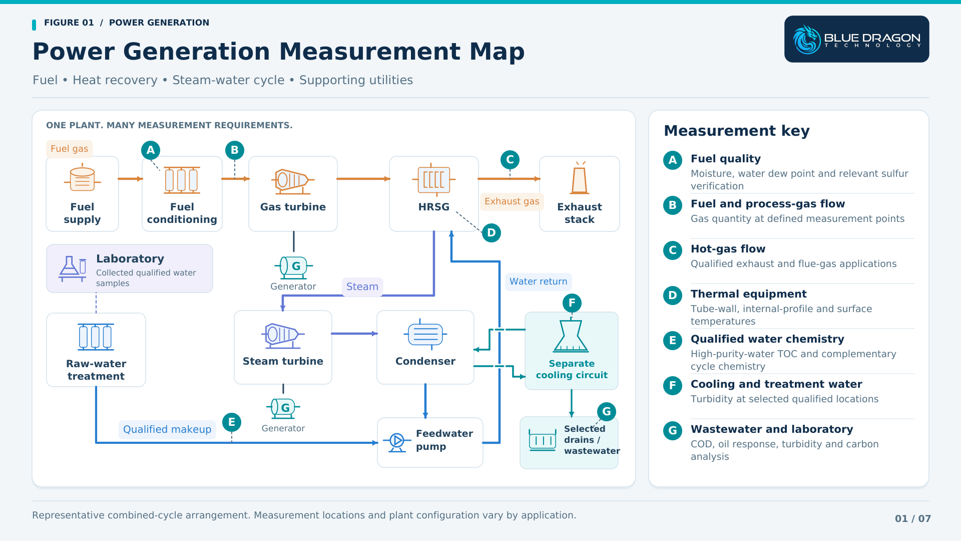
A power plant contains several connected measurement environments. The fuel system establishes what is delivered to the combustion equipment. The thermal system converts fuel energy into useful work and, where applicable, recovers exhaust heat. Water and steam systems carry energy through the cycle, while cooling and wastewater systems support the wider operation.
In a combined-cycle plant, the gas turbine produces power and its exhaust transfers heat to a heat-recovery steam generator, or HRSG. Steam from the HRSG drives the steam turbine. Exhaust gas and steam follow separate paths, connected through heat transfer within the HRSG.
After expansion through the steam turbine, steam is condensed and the water returns through the condensate and feedwater systems. Makeup water replaces losses. Where a water-cooled condenser is used, the cooling-water circuit exchanges heat with the steam-water cycle while remaining a separate water system.
A boiler-based or cogeneration facility has a different arrangement, but the same measurement questions recur:
- Fuel condition: Is the incoming fuel suitable for the equipment and operating requirement?
- Gas quantity: How much fuel or process gas is moving through the defined measurement point?
- Thermal condition: Where do local wall, equipment-surface or internal temperatures vary?
- Water condition: What changes are occurring in treatment, high-purity water, cooling water or wastewater?
Mapping those questions to the plant layout helps establish measurement priorities before model selection. It also separates continuous operating trends from portable investigations and laboratory verification.
Fuel Quality Before Combustion
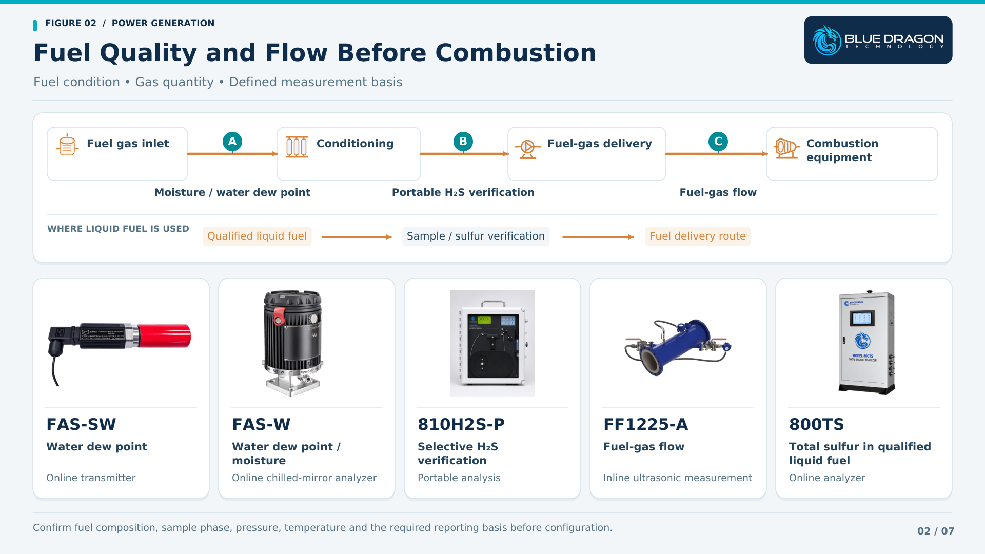
Fuel quality begins with a clear analytical objective. Moisture, selective hydrogen sulfide and total sulfur describe different properties, and their relevance depends on the fuel, supply specification and receiving equipment. The sample phase and expected composition determine how the measurement should be made.
Fuel-Gas Moisture and Water Dew Point
Moisture measurement can help plant teams understand gas dryness, observe changes in conditioning and assess water-condensation risk at defined operating conditions. Water dew point is the temperature at which water condensation begins at the stated pressure; moisture concentration expresses the amount of water on a specified concentration basis.
Blue Dragon provides the FAS-SW Trace Moisture & Dew Point Transmitter and the FAS-W Online Moisture & Dew Point Analyzer for qualified gas applications. FAS-SW provides a compact continuous measurement arrangement, while FAS-W uses an automatic chilled-mirror approach with versions for water dew point, moisture concentration or both.
The application review should establish the gas composition, measurement pressure, expected range and sample-conditioning arrangement. Pressure reduction, cooling, liquid carryover, aerosols, sample-line materials and ambient moisture can affect how representative the delivered sample remains.
The required output should also be explicit. A dew-point result at one pressure and a moisture concentration at reference conditions answer related but different questions. Water-dew-point measurement should be distinguished from hydrocarbon-condensation measurement when defining the fuel-quality scope.
Portable Hydrogen Sulfide Verification
The Model 810H2S-P Portable Hydrogen Sulfide Tape Analyzer supports field verification, commissioning, temporary monitoring and troubleshooting in qualified gas applications. A pressure-fed sample is measured using the tape-based H₂S detection system.
Portable verification can help investigate an unexpected gas-quality result or compare conditions at selected sampling points. The sample composition, concentration range, transport arrangement and operating procedure should be defined before deployment. The portable model is intended for general-purpose, non-hazardous locations; a permanent online installation is a separate scope requiring its own review.
Total Sulfur in Qualified Liquid Fuels
The Model 800TS Online Total Sulfur Analyzer addresses total sulfur using catalytic conversion and ultraviolet fluorescence detection. Its documented standard liquid configuration is oriented toward suitable light-hydrocarbon samples, including diesel and related petroleum fractions.
Where a plant uses a qualified liquid fuel, sulfur analysis can support fuel-quality verification and investigation of changes between supplies. The proposed fuel, range, sampling arrangement and sample handling must be reviewed together. Heavy or otherwise different fuels require specific confirmation of the complete analytical configuration.
Fuel and Process-Gas Flow Measurement
Gas-flow measurement adds quantity information to the fuel-quality picture. A plant may need to follow fuel consumption, compare operating periods, observe flow changes during load transitions or investigate an auxiliary gas service. The measurement point and reporting basis determine how the result can be used.
The FF1225-A Single-Path Inline Ultrasonic Gas Flow Meter is a representative option for qualified fuel and industrial process-gas duties. Ultrasonic transit-time measurement relates the difference in acoustic travel times to gas velocity through the defined measuring geometry.
The final configuration depends on pipe dimensions, gas properties, pressure, temperature, normal and minimum flow, available straight runs and installation access. Flow disturbance, liquid carryover and contamination should be considered when selecting the meter location and evaluating the required performance.
The plant should establish whether it needs actual volumetric flow, flow at defined reference conditions or another specified output. Pressure, temperature and gas-property information may be required by the selected compensation and reporting arrangement.
Fuel-energy calculations require an appropriate heating-value basis as well as a compatible quantity measurement. Useful performance comparisons also require consistent time periods, operating conditions and data quality. Defining these relationships early helps the plant integrate the meter into the intended engineering workflow.
Combustion Exhaust and Flue-Gas Flow
Combustion exhaust creates a different installation challenge from a fuel-gas line. Gas temperature, duct dimensions, velocity distribution, moisture, particulate loading and available access can influence the measurement design and its maintainability.
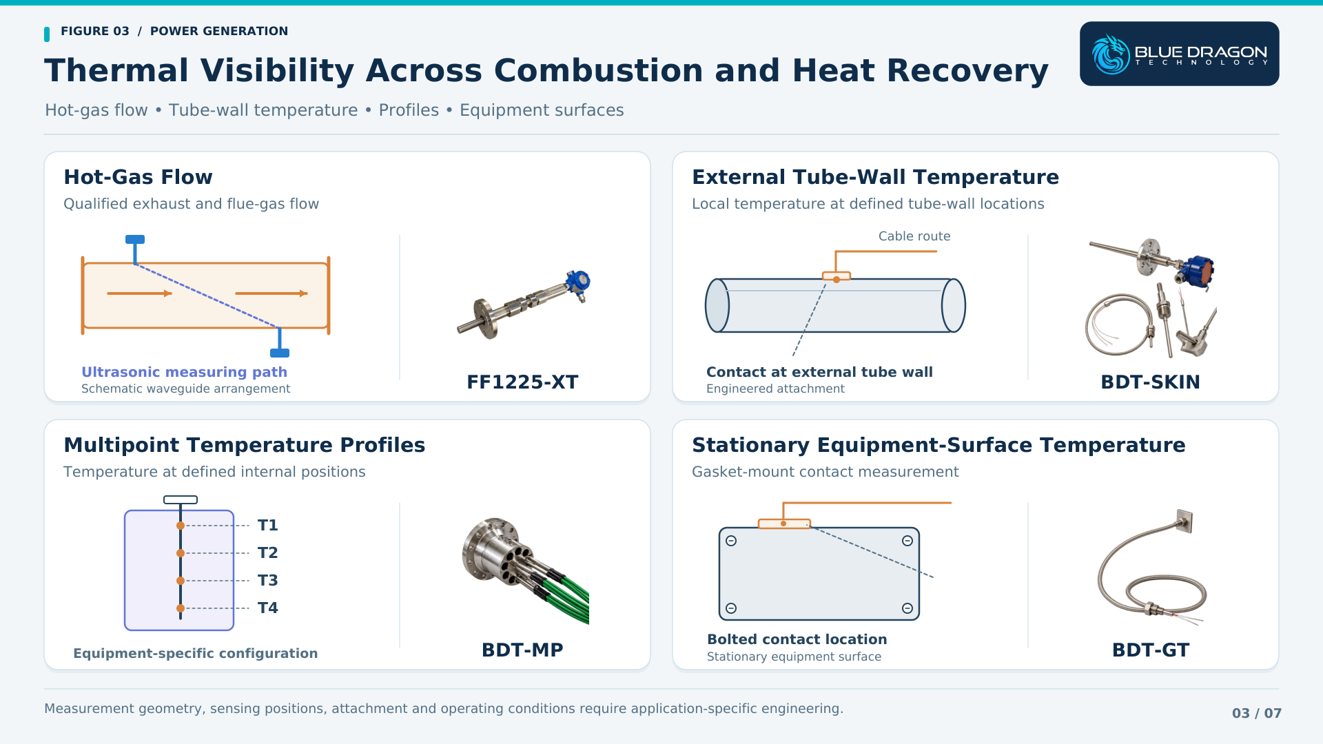
The FF1225-XT Extreme-Temperature Ultrasonic Gas Flow Meter provides an engineered ultrasonic approach for qualified high-temperature gas-flow applications. The waveguide arrangement and measuring geometry must be matched to the actual process conditions.
Exhaust or flue-gas flow information can contribute to operating comparisons and thermal investigations when combined with the relevant temperature, composition and plant data. The useful measurement location depends on the duct layout, flow profile and the question the plant needs to answer.
- Define normal, startup and maximum gas temperatures and pressures.
- Review the duct or pipe geometry, velocity range and expected flow distribution.
- Identify moisture, solids, corrosion and possible deposits.
- Provide installation drawings, access requirements and the intended verification basis.
Gas-flow measurement establishes gas movement. Pollutant concentrations and any regulatory emissions reporting require the appropriate additional measurements, calculations and site acceptance arrangements. The proposed flow meter should be evaluated within that complete system where emissions-related use is intended.
Boiler, HRSG and Equipment Temperature Measurement
Temperature measurement becomes more useful when the physical location of the measurement is clear. External tube-wall temperature, a profile through suitable equipment and the temperature of a stationary machinery surface are different quantities. Each needs an appropriate sensing and mounting arrangement.
External Tube-Wall Temperature
The BDT-SKIN Tube-Skin Thermocouples are engineered for direct external tube-wall temperature measurement. Selected boiler, superheater and heat-recovery applications require review of tube geometry, materials, operating temperature and the surrounding thermal environment.
Measurements at defined tube locations can support comparisons between monitored areas, investigation of localized overheating and assessment of changes over time. Their interpretation should consider load, operating conditions and the limitations of the installed measurement coverage.
Attachment, thermal contact, shielding, expansion allowance, routing and termination are part of the assembly design. A representative installation must tolerate movement and the local thermal environment while maintaining the intended contact with the tube wall. Equipment drawings and installation requirements are therefore important inputs before manufacture.
Multipoint Temperature Profiles
The BDT-MP Multipoint Temperature Assemblies provide multiple thermocouple or RTD sensing points at defined positions within suitable process equipment. A profile can reveal how temperature changes with elevation, depth or another specified dimension.
The application should identify the equipment, required sensing positions and reason for measuring the profile. Insertion length, nozzle geometry, mechanical support, materials, pressure, temperature and termination requirements determine the final design. Each proposed power-plant location needs this engineering review before an assembly is assigned to it.
Equipment-Surface Temperature
The BDT-GT Gasket-Mount Surface Thermocouples provide a compact contact arrangement for suitable bolted or stud-mounted locations on stationary machinery, housings, flanges and other equipment surfaces.
These measurements can support equipment-condition trending where the surface temperature is relevant to the maintenance or operating question. Contact quality, mounting pressure, local heat transfer, vibration, cable routing and the environment must be considered. The gasket-mount product name describes the mounting architecture; the intended surface location should be specified in the application.
Water and Steam-Cycle Chemistry
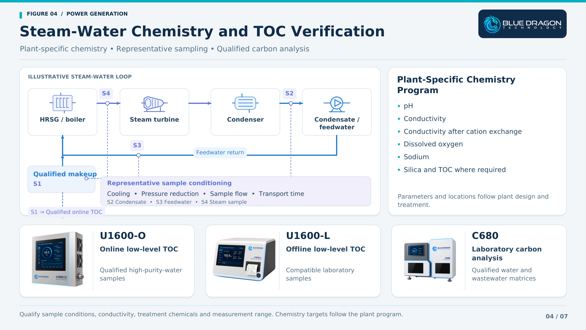
The steam-water cycle carries energy through the plant under conditions that make water chemistry important to equipment operation. Makeup water, condensate, feedwater, boiler water and steam samples have different compositions and monitoring objectives. The plant chemistry program defines which measurements are needed and how their results are interpreted.
Measurement Locations Across the Cycle
Sampling locations should be selected around the plant arrangement, metallurgy, treatment regime and known contamination risks. A result from the makeup-water system cannot automatically be treated as a measurement of condensate or boiler-water condition.
Representative sampling requires attention to extraction, sample transport, cooling, pressure reduction, flow and analysis. Sample-line residence time and the delivered sample condition affect how quickly an analyzer can show a change. Instruments used at a conditioned sample station must be selected for the conditions at that station.
Complementary Chemistry Measurements
A steam-water chemistry program can include pH, specific conductivity, conductivity after cation exchange, dissolved oxygen and sodium, together with additional measurements such as degassed conductivity, silica or TOC where the plant requires them. Each parameter provides a different view of chemical condition or contamination.
The IAPWS guidance on cycle-chemistry monitoring instrumentation provides a framework for selecting monitoring points and techniques for fossil-fired, combined-cycle and industrial plants. The appropriate scope depends on plant type and treatment, with TOC identified among the additional online measurement techniques.
TOC contributes information about organic carbon within this broader framework. Chemistry targets, alarm values and operating responses should follow the plant-specific program and applicable guidance, rather than a universal number applied to every system.
TOC Monitoring and Laboratory Verification
Total organic carbon measurement is useful when the plant needs to follow organic contamination, investigate a water-quality change or verify a qualified sample. The analytical principle and sample matrix determine which TOC platform is appropriate.
Online Low-Level TOC Monitoring
The Model U1600-O Online TOC Analyzer uses UV photocatalytic oxidation and differential conductivity detection for qualified low-level, high-purity-water applications. Suitable makeup or deionized-water duties can be reviewed against the required range, conductivity and sample-delivery conditions.
Online records can help a plant follow changes between laboratory sampling events. To use those records effectively, define the sample point, transport delay, analysis timing, calibration or verification practice and the intended response to a change.
Condensate and chemically treated samples require particular attention to conductivity, treatment chemicals and method compatibility. Cooling, pressure reduction and a compatible measurement range are necessary parts of the review. Being part of a steam-water cycle does not by itself establish sample suitability for a high-purity-water analyzer.
Offline Low-Level TOC Verification
The Model U1600-L Laboratory TOC Analyzer applies the UV oxidation and differential-conductivity approach in an offline laboratory workflow for qualified low-conductivity samples.
Comparison with an online result requires suitable sampling timing and clean, compatible containers. Sample handling, background contamination, holding conditions and method differences should be considered when investigating a discrepancy. Laboratory verification becomes more useful when the sample point and collection time are recorded with the result.
Broader-Matrix Laboratory Carbon Analysis
The Model C680 High-Temperature Combustion TOC Analyzer provides a laboratory approach for qualified water and wastewater samples using catalytic combustion and NDIR carbon-dioxide detection. Separate Total Carbon and Inorganic Carbon paths support TOC calculation, with appropriate NPOC workflows available for suitable samples.
The standard C680 uses manual microsyringe injection. Its role is therefore an offline analytical workflow supporting laboratory verification, treatment assessment and investigation. Method selection, calibration, dilution, inorganic-carbon handling and matrix compatibility remain part of the laboratory procedure.
Cooling Water and Filtration Monitoring
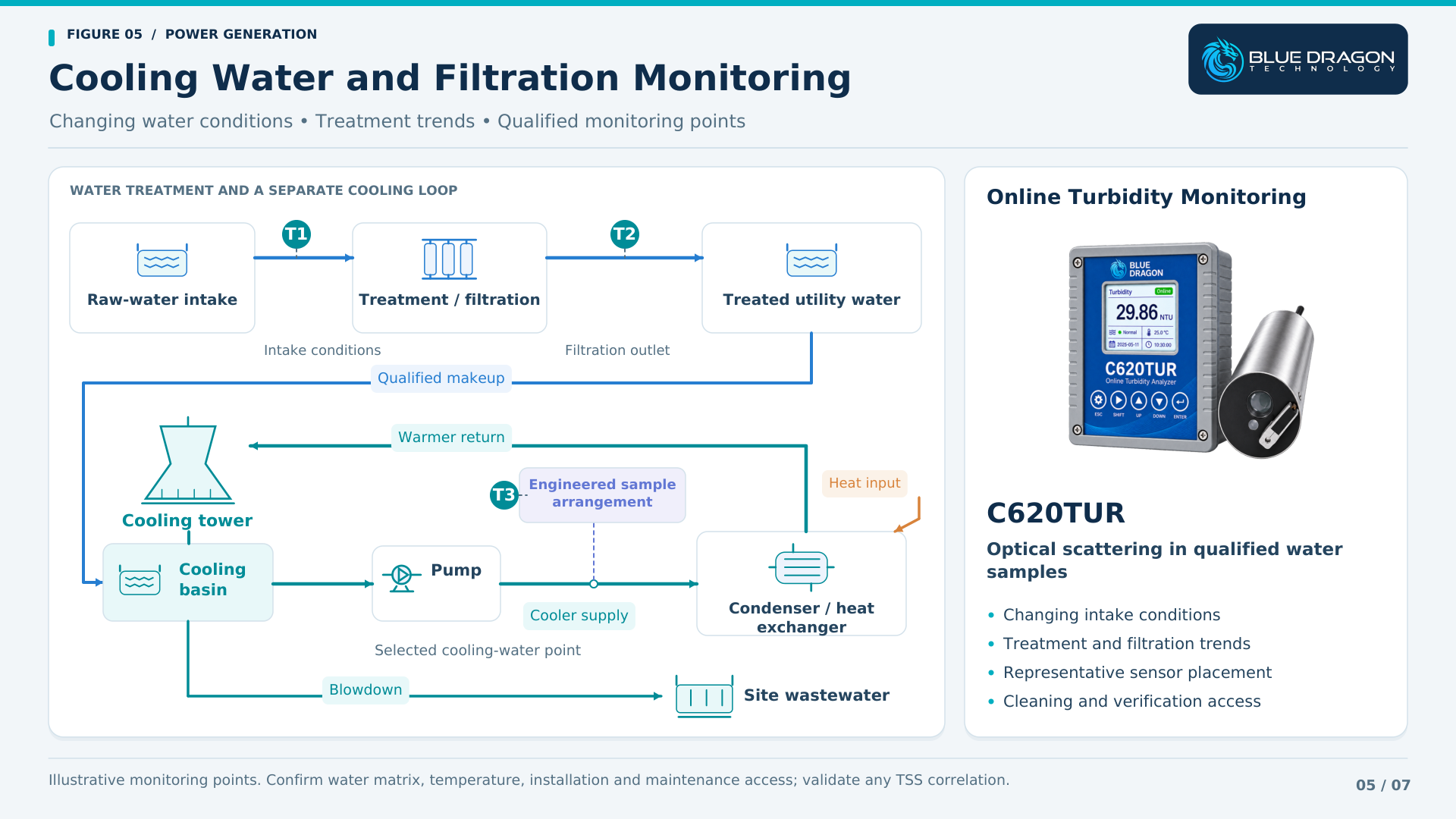
Cooling and utility-water systems introduce a different set of conditions from high-purity makeup water. Incoming water can change with weather, source conditions and treatment operation. Clarification, filtration, reuse and recirculating cooling arrangements each create possible monitoring locations.
The Model C620TUR Online Turbidity Analyzer provides an optical measurement of scattering material in qualified water applications. Its self-wiping sensor and local controller support continuous turbidity indication and configured plant outputs.
At a suitable intake or treatment point, turbidity trends can help identify changing water conditions. Measurements around filtration may support investigation of treatment behavior or breakthrough. Selected cooling-water applications require confirmation of temperature, matrix, mounting and maintenance access.
Bubbles, particle size and characteristics, optical fouling, deposits and sensor position can influence the result. The monitoring point should provide a representative sample and permit routine inspection and verification. Sensor cleaning reduces normal deposit buildup while remaining part of a wider maintenance procedure.
Turbidity is reported on the instrument’s configured optical basis. Any relationship to suspended-solids concentration must be established for the actual water and particle population. Other cooling-water requirements, including dissolved chemistry and treatment control, remain part of the wider water-management program.
Wastewater Monitoring and Laboratory Verification
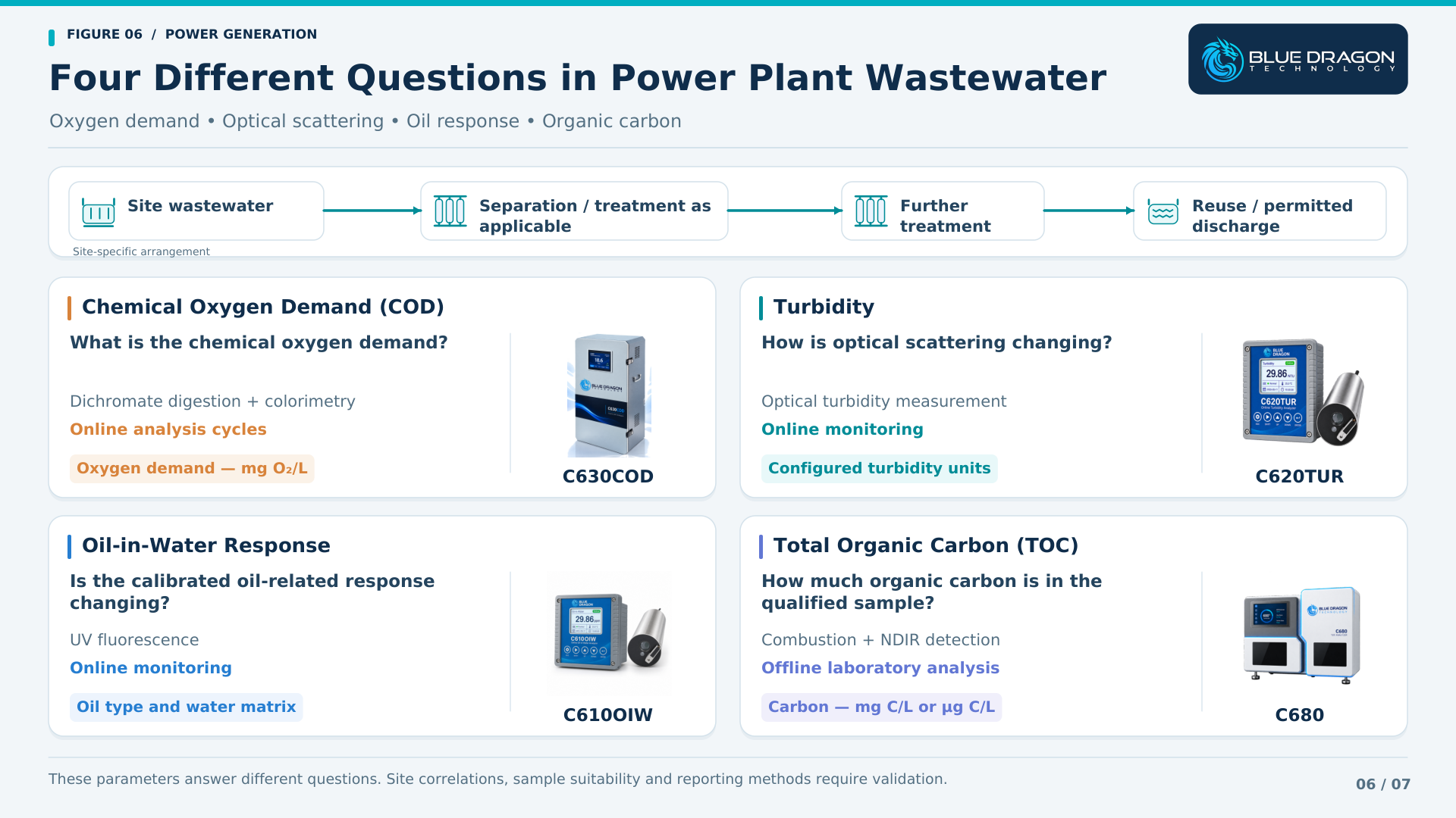
Power-plant wastewater may include treatment residuals, cooling-system blowdown, equipment-area drainage and other site-specific effluents. The plant should define the contributing streams and treatment arrangement before assigning an analyzer. COD, turbidity, oil-in-water and organic carbon provide complementary information.
Chemical Oxygen Demand
The Model C630COD Online COD Analyzer measures CODCr using automatic sample handling, reagent metering, dichromate digestion and colorimetric detection. It provides repeated analytical results according to the configured measurement schedule.
COD describes oxygen demand under the selected chemical method. It can support wastewater-treatment trends and investigation where that method is suitable. Chloride background, sample variability, oxidation behavior, solids handling, reagent management and the delivered range should be reviewed with the plant. The analysis cycle and sample-transport delay determine when a new result becomes available.
Turbidity in Treatment and Discharge-Related Streams
C620TUR can provide solids-related optical trends at qualified wastewater locations. Representative placement, bubbles, fouling, cleaning and verification remain important. Results should be interpreted against the treatment process and any validated site relationship to other parameters.
Oil-in-Water Response
The Model C610OIW Online Oil-in-Water Analyzer uses UV fluorescence for hydrocarbon-related monitoring in suitable water streams. Potential plant applications include investigation of oil-bearing drainage or other qualified wastewater contamination.
Response depends on the oil type, aromatic content, calibration basis, sample matrix and optical condition. The site should establish the expected contaminants and suitable reference comparison before using the result for an operating or reporting decision.
Laboratory Organic Carbon Analysis
C680 supports laboratory carbon analysis of qualified wastewater samples. Results can help compare treatment stages, investigate an online trend or assess changes in the contributing streams, using an appropriate sample preparation and validated analytical procedure.
Matching Instruments to Power Plant Areas
The following table connects representative plant areas with measurement objectives and potentially relevant technologies. It provides an application map for initial discussion. The final range, sampling system, installation and supplied configuration follow review of the actual plant requirement.
| Plant Area | Measurement Need | Measurement Technology | Representative Blue Dragon Solutions |
|---|---|---|---|
| Fuel-gas receiving and conditioning | Moisture and water dew point | Continuous transmitter or chilled-mirror analysis | FAS-SW, FAS-W |
| Fuel-gas field investigation | Selective H₂S verification | Portable tape-based gas analysis | 810H2S-P |
| Qualified liquid-fuel systems | Total sulfur | Online catalytic conversion and UV fluorescence | 800TS |
| Fuel and process-gas lines | Gas flow | Inline ultrasonic gas-flow measurement | FF1225-A |
| Qualified hot exhaust and flue-gas duties | Extreme-temperature gas flow | Engineered waveguide ultrasonic measurement | FF1225-XT |
| Boiler and HRSG tubes | Local external tube-wall temperature | Engineered tube-skin thermocouples | BDT-SKIN |
| Suitable equipment and stationary surfaces | Temperature profiles and surface temperature | Multipoint assemblies and gasket-mount thermocouples | BDT-MP, BDT-GT |
| Qualified high-purity water | Low-level TOC monitoring and verification | Online and offline UV oxidation with differential conductivity | U1600-O (online), U1600-L (laboratory) |
| Plant water and wastewater laboratory | Qualified carbon analysis | Laboratory combustion and NDIR detection | C680 (laboratory) |
| Intake, filtration and cooling-water systems | Turbidity | Online optical turbidity measurement | C620TUR |
| Wastewater treatment and investigation | COD, turbidity, oil response and TOC | Online COD cycles, optical sensors and laboratory carbon analysis | C630COD, C620TUR, C610OIW; C680 (laboratory) |
Technical Qualification: Why Application Review Comes First
A parameter name provides a starting point, but the actual application determines the instrument design and installation. Two gas streams requiring moisture measurement may have different pressures, contaminants and sampling needs. Two water samples requiring TOC may need different oxidation and detection methods.
A useful application review connects the measurement objective with the following engineering inputs.
1. Measurement Objective
Define the required parameter, reporting basis, range, response and intended use. Establish whether the result supports an operating trend, an investigation, laboratory verification, an alarm or another plant decision.
2. Stream Composition and Sample Matrix
Provide representative gas composition or water chemistry, including expected contaminants. Identify free liquids, particles, aerosols, oil, treatment chemicals and possible interferents that may affect measurement or sample handling.
3. Pressure and Temperature
Include normal operation, startup and upset conditions. For sampled measurements, specify both process conditions and the conditions expected at the analyzer after any cooling, pressure reduction or other conditioning.
4. Sampling and Conditioning
Review extraction, transport distance, residence time, sample flow, filtration and conditioning. Define how the system will maintain a representative sample and how total response time fits the operating requirement.
5. Installation Geometry
Provide pipe or duct dimensions, available straight runs, tube drawings, nozzles, insertion positions and mounting details. Include thermal movement, supports, sensor routing and access for installation and maintenance.
6. Materials and Installation Environment
Define wetted-material requirements, corrosion risks, ambient conditions and area classification. Certification and installation requirements should be established for the complete proposed arrangement and delivered configuration.
7. Calibration and Verification
Specify standards, reference methods, comparison procedures and record requirements. Establish maintenance intervals, consumables, cleaning arrangements and practical access for verification of the installed measurement.
8. Outputs and Plant Integration
Identify required analogue signals, digital communications, alarm functions, historian records and interface responsibilities. Any operating action or interlock requires the site-defined control and engineering basis.
Building a Coordinated Power Generation Measurement Package
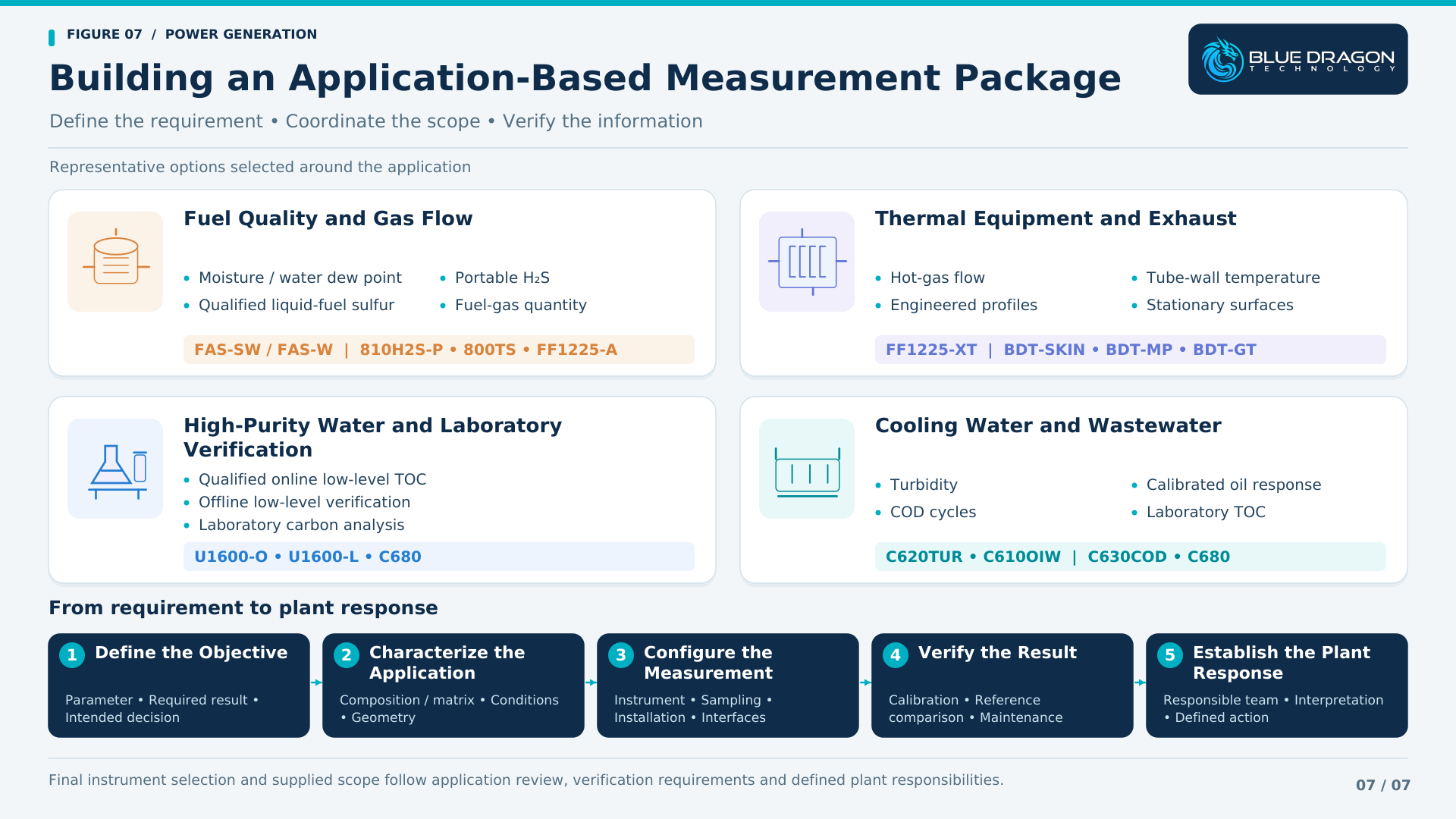
A coordinated scope can begin with one defined measurement problem. Additional instruments can be reviewed where they provide information that helps the plant understand the same system or investigate connected operating conditions.
Fuel Quality and Gas Flow Package
Combine qualified moisture and water-dew-point monitoring with fuel-gas flow. Add portable H₂S verification where relevant, and liquid-fuel sulfur analysis where the fuel and analytical objective justify it. The scope follows the actual fuel supply and receiving equipment.
Thermal Equipment and Exhaust Package
Review selected tube-wall temperatures, engineered temperature profiles, stationary equipment-surface measurements and hot-gas flow. Drawings, measurement positions and operating conditions determine which assemblies and measuring arrangements are appropriate.
High-Purity Water and Laboratory Verification Package
Evaluate online low-level TOC monitoring and offline verification for compatible high-purity samples. Use a suitable laboratory carbon platform where broader water or wastewater matrices require a different analytical approach. Coordinate this scope with the plant chemistry program.
Cooling Water and Wastewater Package
Select turbidity, oil-related response, COD or laboratory TOC around defined water-treatment questions. Sampling locations, matrix compatibility, analytical timing and reference comparison determine how the measurements can support treatment and investigation.
Coordinated Plant Scope
For a wider project, combine the selected packages with a shared review of sampling, installation, utilities, communication, documentation and verification. Define the supplied scope and plant responsibilities so that each measurement has an owner, a maintenance plan and an intended use.
Information to Provide Before Instrument Selection or Quotation
Providing the available application information at the beginning of a project helps identify suitable technologies and the questions that still need to be resolved. For an initial review, share:
- Plant type and process or equipment area
- Measurement objective and intended use of the result
- Gas, liquid, water or equipment details
- Representative composition, fuel properties or water matrix
- Required measurement range and response
- Normal, minimum and maximum pressure and temperature
- Pipe, duct, tube or equipment drawings and dimensions
- Proposed sampling arrangement and installation location
- Materials, area classification and environmental requirements
- Required signals, communications and documentation
- Calibration or reference-method requirements
- Project location and schedule
A complete specification is not necessary to begin the discussion. Blue Dragon can review the available information, identify missing inputs and define the next engineering step before final configuration and quotation.
Frequently Asked Questions About Power Generation Instrumentation
Which measurements support power generation beyond the turbine?
Relevant categories include fuel moisture and sulfur where required, gas flow, boiler and HRSG tube temperatures, engineered equipment temperatures, steam-water chemistry, cooling-water quality and wastewater analysis. The priorities depend on plant type, process conditions and the decisions the measurements must support.
What is the difference between moisture concentration and water dew point?
Moisture concentration reports the amount of water on a defined concentration basis. Water dew point reports the temperature at which water condensation begins at the stated pressure. The required output and measurement pressure should be specified when reviewing a fuel-gas application.
Where is portable H₂S verification useful?
Portable H₂S analysis can support commissioning, field verification, temporary monitoring and troubleshooting at qualified sampling points. The 810H2S-P requires a suitable sample and general-purpose, non-hazardous installation environment. A permanent online installation needs a separately defined scope.
How does fuel-gas flow differ from exhaust-gas flow measurement?
Fuel and exhaust services can differ substantially in temperature, pressure, duct or pipe geometry, flow distribution and contaminants. The measurement architecture and installation must follow those conditions. FF1225-A and FF1225-XT represent different ultrasonic configurations for qualified applications.
What do tube-skin thermocouples measure?
Tube-skin thermocouples measure local external tube-wall temperature at defined locations. BDT-SKIN assemblies are engineered around the tube geometry, attachment, thermal environment, movement and routing. The installed readings should be interpreted with the equipment operating conditions and measurement coverage.
Does TOC provide a complete steam-water chemistry assessment?
TOC provides organic-carbon information. A plant chemistry program also considers other parameters, potentially including pH, conductivity, conductivity after cation exchange, dissolved oxygen, sodium and silica. The required monitoring points and techniques depend on plant design, treatment and applicable guidance.
How do online TOC and laboratory TOC workflows differ?
Online measurement produces records from a defined sample-delivery system, while laboratory analysis tests collected samples under a controlled procedure. U1600-O and U1600-L address qualified low-level, low-conductivity samples in different workflows; C680 supports qualified laboratory combustion-based carbon analysis.
Can COD, TOC, turbidity and oil-in-water results be converted directly?
These parameters measure different properties using different methods. A site may establish a useful correlation for a defined wastewater, but it must be validated against representative samples and the intended use. Changes in composition can change that relationship.
From Fuel Conditions to Reliable Generation
Power generation brings fuel, gas movement, thermal equipment and water systems together in one operating environment. Each introduces a different measurement question, and each requires a representative installation and a suitable interpretation of the result.
- Fuel-quality measurements help establish incoming fuel conditions.
- Gas-flow measurements provide visibility of fuel, process-gas and qualified hot-gas movement.
- Engineered temperature assemblies reveal local tube-wall, internal-profile and equipment-surface conditions.
- Water-quality instruments support treatment monitoring, contamination investigation and the wider chemistry program.
- Laboratory analysis provides complementary verification and investigation data.
The value comes from connecting the right measurement point to an operating, maintenance or water-quality decision. Sample suitability, installation, verification and a defined plant response are what make the information useful.
Blue Dragon Technology supports individual measurement requirements and coordinated scopes across fuel systems, combustion and heat recovery, qualified water applications, cooling systems and wastewater.
Discuss Your Power Generation Measurement Requirements
Blue Dragon Technology can review individual measurement points or a coordinated plant scope across fuel quality, gas flow, engineered temperature measurement, water-quality monitoring and laboratory verification.
Share the plant area, measurement objective, sample or equipment details, operating conditions, installation requirements and project schedule where available. These inputs help define the appropriate technical review and proposed configuration.
Discuss Your Application
Request a Quote
Contact Blue Dragon
Blue Dragon Technology
Measure. Control. Optimize.