Available Available for application review and quotation
Water Quality & Organic Carbon Series
Model C610OIW

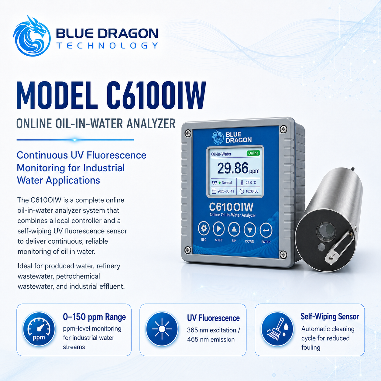
Model C610OIW Online Oil-in-Water Analyzer

Continuous ppm-level oil-in-water trending with a 365 nm UV fluorescence sensor, self-wiping optics, local controller, and plant outputs.

Brand: Blue Dragon Technology Supply & support: Blue Dragon Technology
Product Overview

Purpose-built measurement, clearly presented.

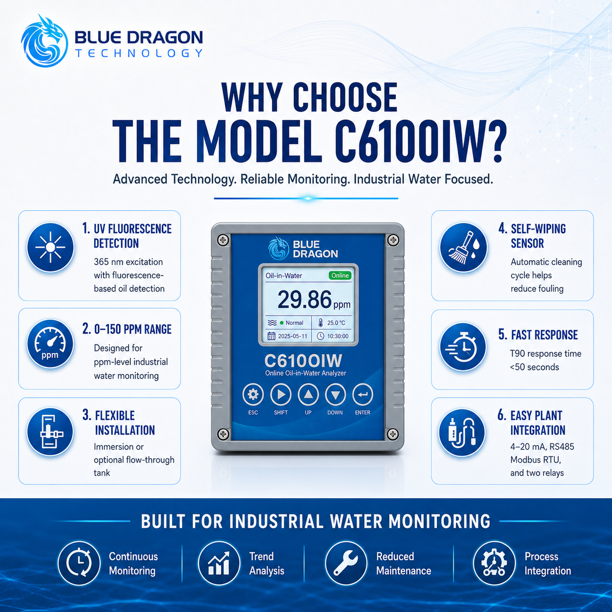
The Model C610OIW is an online monitoring and process-control system for ppm-level oil response in industrial water. The standard package combines a 0–150 ppm self-wiping UV fluorescence sensor, local controller/transmitter, 10 m sensor cable, and plant communication outputs.

The standard 365 nm sensor is best suited to heavy oils, crude-oil fractions, produced water, refinery wastewater, and dirty or turbid industrial streams. Quantitative agreement with a laboratory method requires site-specific calibration using representative samples.

Distinctive Capabilities

  • Rapid continuous trending and alarm indication for ppm-level heavy-oil and crude-oil contamination
  • Self-wiping optical window for reduced fouling and lower routine cleaning demand
  • Flexible immersion deployment or optional pressure-free flow-through installation
  • Local display, calibration, alarms, analogue output, and Modbus communication
  • Field calibration using representative process samples
Performance & Technical Data

The measurement method and the values that matter.

How it measures

Measurement Principle

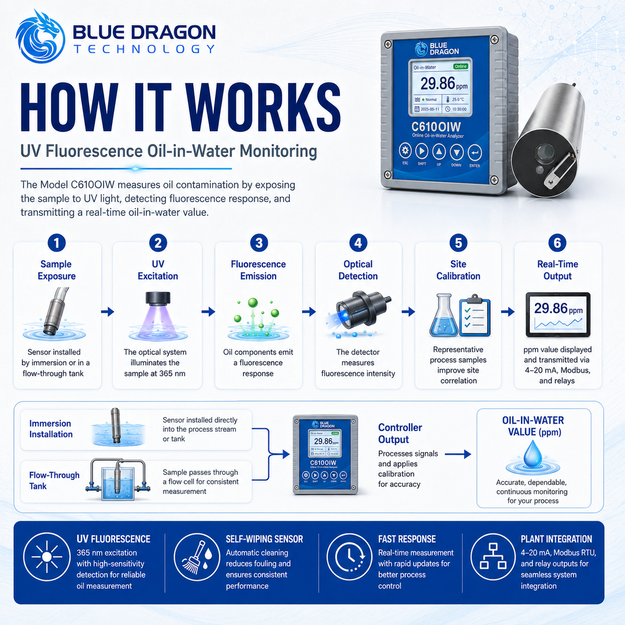
The sensor excites fluorescent hydrocarbon compounds at 365 nm and detects emitted light near 465 nm. Fluorescence intensity is converted to an oil-in-water response using the active calibration. A motorized wiper periodically cleans the optical window to reduce fouling. Because fluorescence varies by oil type and water matrix, the indicated concentration must be correlated with representative site samples when laboratory agreement is required.

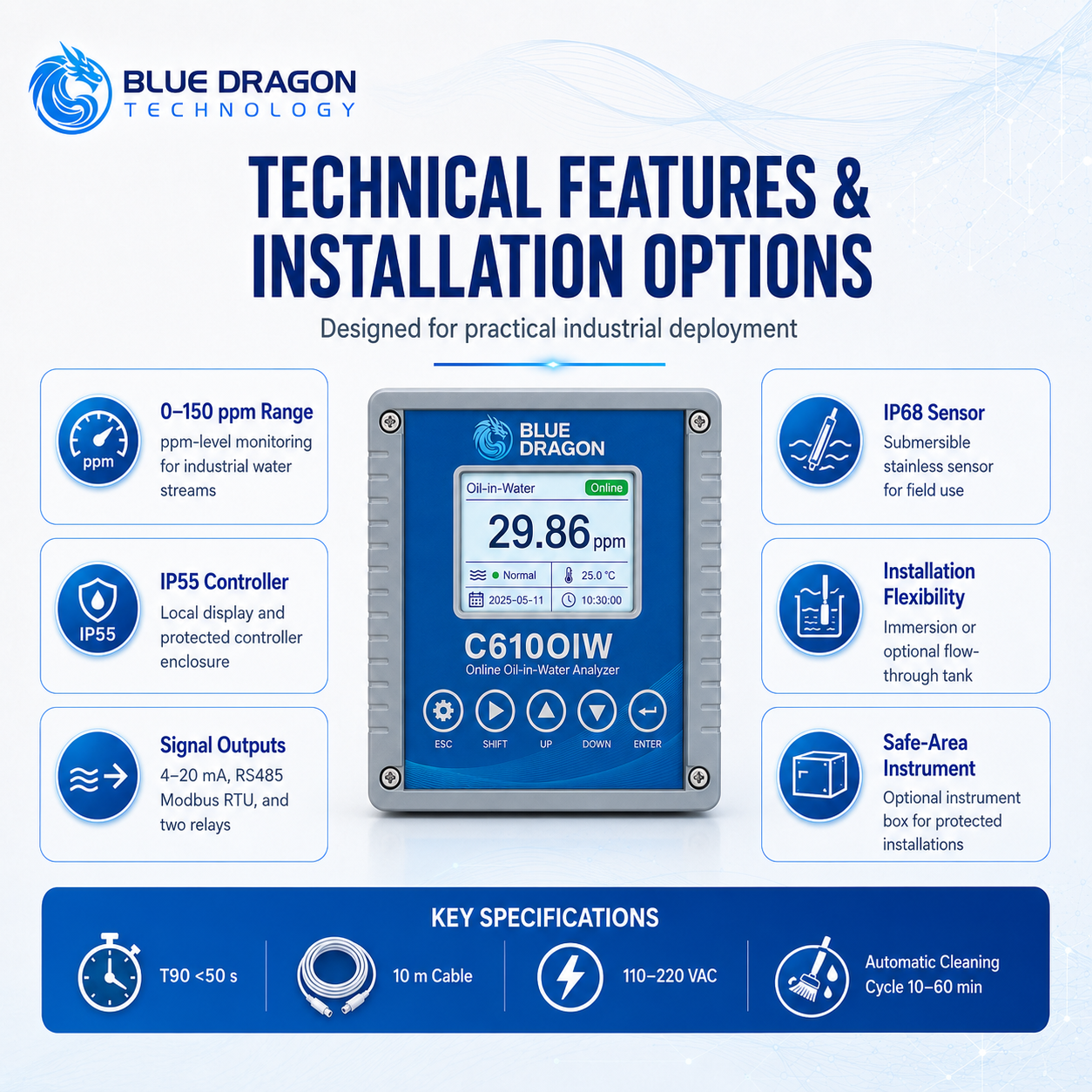
Analysis TimeT90 less than 50 seconds, excluding sample transport
Measurement ParametersOil-in-water fluorescence response
Standard measurement range0–150 ppm
Excitation / emission365 nm / approximately 465 nm
Resolution0.01 ppm
Published reference accuracy±5% of measured value under factory reference conditions; not universal across oil types

Complete Technical Data

Published reference linearity
R² greater than 0.999 under reference conditions
Calibration
Zero, one-point, or two-point; representative site calibration recommended
Sensor cleaning
Automatic self-wiping; default 30-minute interval, adjustable 10–60 minutes
Sensor temperature
0–50 °C
Sensor protection
IP68
Maximum immersion depth
30 m
Sensor body pressure rating
Up to 4 bar; installation and seals govern
Standard sensor material
316L(Ti) stainless steel
Sensor dimensions
Approximately Ø45 × 190.8 mm
Standard sensor cable
10 m
Controller supply
110–220 VAC
Controller protection
IP55
Controller environment
0–55 °C, relative humidity no more than 80%
Analogue output
One 4–20 mA output
Digital communication
RS-485 Modbus RTU
Relay outputs
Two configurable changeover relays
Availability
Available
Industrial Use

Applications and industries.

Typical Applications

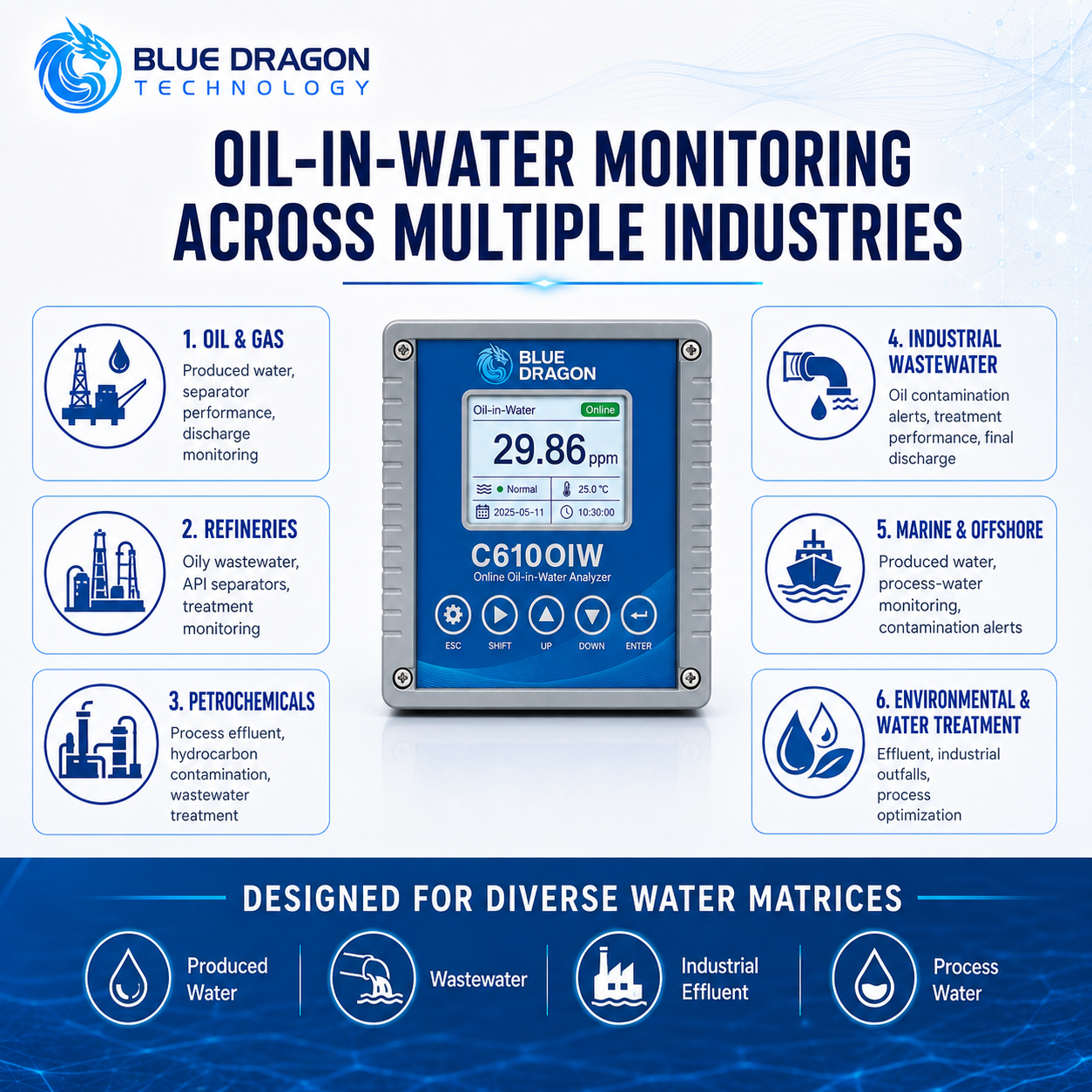
Produced-water and oilfield water monitoringRefinery wastewater, separator performance, and oil-leak detectionPetrochemical and chemical-plant effluentHeavy-oil, crude-oil, and industrial wastewater trendingProcess-water contamination alarms and environmental discharge monitoringOil-in-Water MonitoringProduced-Water Oil Monitoring

Industries Served

Chemical ProcessingEnvironmental Monitoring & ComplianceFertilizers & ChemicalsOil & GasPetrochemicalsPower GenerationRefiningWater & Wastewater
Engineering & Integration

Built for specification, installation, and long-term operation.

Practical requirements for matching the oil and water matrix, selecting immersion or flow-through installation, protecting the controller, calibrating the response, and maintaining the optical system.

Standard package0–150 ppm self-wiping sensor, controller, 10 m cable, manual, and factory test report
Sensor deploymentImmersion or optional pressure-free overflow flow-through tank
Plant integration4–20 mA, RS-485 Modbus RTU, and two configurable relays
Calibration basisOil- and matrix-specific site calibration with representative samples

System Configuration

The standard analyzer is a controller-and-sensor system; installation hardware and sample conditioning are selected separately.

  • StandardLocal controller/transmitter with display, setup, calibration, alarm, and output functions
  • Standard10 m sensor cable, product manual, and factory test report
  • OptionalFlow-through tank, mounting hardware, instrument box, extended cable, calibration kit, and spare wiper kit
  • OptionalApplication-reviewed titanium-alloy housing for high-salinity service
  • Application DependentSensor wavelength and range must match the target oil type and concentration
  • OptionalOverflow-type flow-through tank for a controlled, pressure-free bypass sample

Sensor & Sample Interface

The sensor can be immersed directly or installed in a low-pressure bypass, but representative presentation and freedom from bubbles are critical.

  • StandardDirect immersion in tanks, channels, basins, or suitable water streams
  • OptionalOverflow-type flow-through tank operated as a pressure-free measurement chamber
  • Application DependentAvoid bubbles, foam, wall contact, heavy sediment accumulation, and unstable oil-water mixtures
  • Application DependentHigh suspended solids and severe turbidity can increase optical interference; approximately 500 NTU is a practical review threshold
  • Application DependentSample transport and mixing add to the sensor response time
  • Project EngineeredPretreatment may be added where the process cannot provide a stable representative sample

Installation & Utilities

Install the IP68 sensor in the water stream and protect the IP55 controller in a safe, accessible environment.

  • StandardController may be wall- or panel-mounted within 0–55 °C and no more than 80% relative humidity
  • OptionalInstrument box or analyzer cabinet where outdoor, washdown, marine, corrosive, or harsher conditions exceed IP55
  • StandardRoute the sensor cable without tensile load, sharp bends, abrasion, or water entry at terminations
  • Application DependentStandard configuration is non-explosion-proof and intended for safe-area installation
  • The IP68 sensor can be installed directly by immersion or inside an optional overflow-style flow-through tank.
  • The IP68 sensor may be installed directly in tanks, channels, basins, or suitable process-water streams.

Controller & Communications

The controller provides local indication and common plant outputs for trending, alarms, and remote monitoring.

  • StandardTwo configurable changeover relays for alarm or control logic
  • StandardLocal calibration, range, alarm, wiping interval, and output setup
  • Application DependentRelay contact rating and full register map are governed by the supplied controller label and project documentation
  • The controller provides 4–20 mA output, RS485 Modbus RTU communication, and two relays for connection to PLC, SCADA, DCS, and alarm systems.
  • Contact Blue Dragon Technology to discuss your oil type, water matrix, concentration range, turbidity, installation conditions, calibration requirements, flow-through configuration, instrument enclosure, and plant integration requirements.

Calibration & Quality Control

UV fluorescence response is specific to the oil type, water chemistry, salinity, solids, and process condition.

  • StandardZero, one-point, and two-point calibration functions
  • StandardUse stable, representative process samples and a defined laboratory comparison method when quantitative correlation is required
  • StandardVerify the 4–20 mA scale and alarm setpoints after calibration
  • Application DependentFactory accuracy and linearity values apply to the reference solution and are not universal performance guarantees
  • Application DependentRecalibrate when the oil source, water matrix, optical window, sensor, or application conditions change materially
  • UV fluorescence response depends on oil composition and the water matrix. Crude oils, heavy oils, refined oils, process chemicals, and additives may produce different fluorescence responses at the same actual oil concentration.

Cleaning & Maintenance

The self-wiping mechanism reduces fouling but does not eliminate inspection, cleaning, and consumable replacement.

  • StandardDefault wiping interval is 30 minutes and may be adjusted from 10 to 60 minutes
  • StandardInspect the optical window, wiper arm, cable, seals, and controller routinely
  • Application DependentNitrile-rubber wiper element is normally inspected or replaced every 3–6 months
  • StandardExpected wiping-motor service life exceeds five years under normal conditions
  • StandardClean deposits using approved methods without scratching the optical window
  • OptionalKeep a spare wiper kit and sensor cable for critical or remote installations

Interferences & Application Considerations

The C610OIW is an online process indicator, not a certified laboratory reference method.

  • StandardStandard controller and sensor package is non-explosion-proof and intended for safe areas
  • Project EngineeredClassified-area use requires a separately approved and certified installation solution
  • Application DependentOil type, salinity, turbidity, solids, bubbles, foam, solvents, and emulsion stability affect response
  • Application DependentClear low-oil water, light refined oils, ppb-level targets, or BTEX-focused measurement may require the alternative 255 nm sensor
  • StandardIsolate controller power before wiring or disconnecting the sensor
  • StandardDo not assume the sensor-body pressure rating makes an optional flow-through tank suitable for pressurized service
Application Review

Application Engineering Notes

Measurement basis

The C610OIW reports a fluorescence response calibrated in ppm. Different oils can produce different fluorescence responses at the same actual concentration, so site correlation is required when results must agree quantitatively with a laboratory method.

Supply scope

The standard package includes the controller, 0–150 ppm self-wiping sensor, 10 m cable, operating manual, and factory test report. A flow-through tank, instrument enclosure, pretreatment, mounting hardware, extended cable, calibration kit, spare wiper kit, and titanium housing are optional or project-specific.

Application fit

The standard 365 nm system is intended primarily for heavy-oil, crude-oil, produced-water, refinery-wastewater, and dirty industrial-water applications. Clear-water and low-range light-oil applications may require an alternative sensor configuration.

Project Delivery

Project Integration & Support Scope

Blue Dragon reviews the measurement objective, interfaces, documentation, commissioning, and lifecycle requirements as part of project configuration. The scope below identifies the principal items to confirm before order placement.

Measurement Objective
Continuous ppm-level oil-in-water monitoring for produced water, refinery and industrial wastewater, hydrocarbon-leak detection, separator performance, process trending, and discharge-risk reduction.
Signal Outputs
The standard controller provides one scalable 4-20 mA output, RS-485 Modbus RTU, and two configurable changeover relays for alarm or control logic.
Data Integration
The controller supports local indication, calibration, range and alarm setup, wiping control, and connection to PLC, DCS, SCADA, historian, or environmental monitoring systems through 4-20 mA and Modbus RTU.
Alarms & Diagnostics
The project can configure high-oil alarms, relay logic, communication status, and maintenance response. Sensor fouling, unstable sample presentation, and calibration changes should be addressed through the site operating and maintenance procedure.
Documentation
The package may include the product sheet, manual, factory test report, sensor and controller wiring, installation arrangement, output and relay details, calibration guidance, and FAT or SAT records as ordered.
Commissioning Support
Commissioning can include installation and sample-flow verification, baseline and representative-oil checks, site calibration, 4-20 mA scaling, Modbus communication, relay testing, wiping setup, operator training, and handover records.
Lifecycle Support
Lifecycle support covers optical-window cleaning, wiper inspection and replacement, sensor and cable checks, site calibration, controller troubleshooting, spare parts, repairs, and long-term technical assistance.
Online Analyzer Configuration

Sample System & Online Analyzer Readiness

Reliable online measurement depends on the process interface as well as the analyzer. Confirm the following application data before final configuration and quotation.

Sample Type & Phase
Produced water, refinery wastewater, industrial wastewater, process water, cooling water, drainage water, or another aqueous stream containing fluorescent hydrocarbon contamination. The standard 365 nm sensor is intended primarily for heavy oils, crude-oil fractions, produced water, and dirty industrial streams.
Measurement Range
Confirm the normal and peak oil response, required alarm points, reporting units, laboratory comparison method, and target detection level. The standard range is 0-150 ppm with 0.01 ppm resolution; clear water, light refined oils, ppb-level targets, or BTEX-focused work may require a different sensor.
Sample Conditions
Provide water temperature, pressure, flow, salinity, suspended solids, turbidity, bubbles, foam, emulsion stability, surfactants, oil type, chemical additives, and fouling tendency. Different oils can produce different fluorescence responses at the same actual concentration.
Sample Handling
Define direct immersion or a pressure-free bypass arrangement, representative mixing, optional overflow tank, filtration or pretreatment, cleaning access, drain, return, and sensor mounting. Avoid bubbles, foam, wall contact, heavy sediment, and unstable phase separation.
Installation Area
Confirm tank, channel, basin, bypass, indoor or outdoor location, ambient conditions, controller protection, cable route, service access, safe-area or classified-area requirements, and whether an instrument box or analyzer cabinet is required.
Utilities
Provide 110-220 VAC for the standard controller, an accessible disconnect, sample or bypass flow as applicable, drain or return, cleaning provisions, calibration materials, and communication cabling. The standard controller and sensor are non-explosion-proof.
Response Requirement
Define whether the measurement is used for discharge alarm, separator or treatment control, hydrocarbon-leak detection, environmental trending, or maintenance response. The published sensor T90 is less than 50 seconds, excluding sample transport and mixing delay.
Integration Requirement
Confirm 4-20 mA scaling, RS-485 Modbus RTU settings, relay assignments, alarm setpoints, PLC or DCS tags, historian requirements, and responsibility for wiring and cause-and-effect logic.
Commissioning Requirement
Verify representative sample presentation, immersion or bypass conditions, bubbles and solids, sensor cleaning, baseline, representative-oil calibration, 4-20 mA scaling, Modbus communication, relay logic, wiping interval, and laboratory correlation where quantitative agreement is required.
Operational Visibility

Alarm & Diagnostic Matrix

The C610OIW controller supports local indication, two configurable relays, one 4–20 mA output, and RS-485 Modbus RTU. Optical and maintenance conditions must also be evaluated against representative process samples.

Project Setpoint means the limit is selected for the ordered application. Recommended severity is generic website guidance; the site alarm philosophy is final.

High oil-in-water response

Process Severity: Critical
Trigger / Basis
The calibrated fluorescence result reaches the configured high Project Setpoint.
Instrument Response
The controller indicates the value and operates a configured relay; 4–20 mA and Modbus continue to report available data.
Operator Response
Confirm the process condition, inspect for bubbles or fouling, and verify with the approved representative sample and laboratory method.
Reset & Ownership
The DCS or PLC owns process action. Relay assignment, delay, latching, fail-safe logic, and reset are project configured.

Low oil-in-water response

Process Severity: Advisory
Trigger / Basis
The result reaches a configured low Project Setpoint where low-limit monitoring is required.
Instrument Response
The controller indicates the value and can operate the second configurable relay when assigned to a low limit.
Operator Response
Confirm sample presentation, calibration, oil and water matrix, sensor immersion, and that the value is not caused by bubbles or poor mixing.
Reset & Ownership
Normally DCS or PLC owned. Use, latching, and reset are defined by the project alarm philosophy.

Result invalid, unstable, or out of range

Measurement Quality Severity: Warning
Trigger / Basis
The optical response is outside the configured range or cannot be accepted as a stable representative result.
Instrument Response
Local status or an implausible or unstable output identifies that the result requires investigation.
Operator Response
Check sample mixing, bubbles, foam, solids, sensor position, window cleanliness, calibration, and output range.
Reset & Ownership
Instrument status originates locally; data-quality and hold-last or fail-safe behavior are defined in the receiving system.

Optical window cleaning required

Maintenance Severity: Advisory
Trigger / Basis
Inspection, drift, or failed verification indicates deposits despite programmed self-wiping.
Instrument Response
The automatic wiper continues at the configured interval; no universal separate cleaning alarm is assumed.
Operator Response
Inspect and clean the optical window with an approved non-scratching method, then verify the response before return to service.
Reset & Ownership
Operator maintenance owned. Reset or return to service follows a successful inspection and verification.

Wiper service required

Maintenance Severity: Warning
Trigger / Basis
The wiper is damaged, hardened, deformed, obstructed, or no longer cleans the optical window effectively.
Instrument Response
Automatic cleaning becomes ineffective and measurement drift or instability can develop.
Operator Response
Isolate safely, inspect the arm and motor, replace the approved wiper element, and confirm a complete cleaning cycle.
Reset & Ownership
Operator maintenance owned; any remote advisory requires project logic because no universal relay assignment is assumed.

Calibration or verification failed

Quality Control Severity: Warning
Trigger / Basis
A zero, one-point, two-point, or site-correlation check does not meet the approved acceptance criterion.
Instrument Response
The result must not be accepted as quantitatively correlated until a valid calibration or verification is completed.
Operator Response
Check reference sample stability, laboratory basis, oil and water matrix, window condition, bubbles, range, and calibration entries.
Reset & Ownership
Quality-system owned. Return to service requires an approved successful verification.

Sensor, cable, or controller fault

Analyzer Severity: Critical
Trigger / Basis
The controller cannot obtain a valid signal from the sensor or identifies a controller or sensor condition.
Instrument Response
Local status and plant outputs indicate unavailable or invalid measurement according to the delivered controller behavior.
Operator Response
Inspect power, cable routing, terminations, seals, sensor condition, connectors, and the active local diagnostic.
Reset & Ownership
Analyzer owned; external fail-safe action and reset are defined by the approved I/O and cause-and-effect.

4–20 mA signal fault

Integration Severity: Warning
Trigger / Basis
The receiving system detects a missing, invalid, or non-updating analogue signal.
Instrument Response
Local measurement may remain available while the plant analogue input is unavailable.
Operator Response
Check output scaling, loop power and load, polarity, terminals, cabling, controller simulation, and DCS input configuration.
Reset & Ownership
The DCS or PLC owns loop-fault detection and reset; the controller owns output generation.

Modbus communication loss

Integration Severity: Warning
Trigger / Basis
RS-485 Modbus data stops updating or the receiving system cannot communicate with the controller.
Instrument Response
Local display and measurement can remain available while remote digital data is stale or absent.
Operator Response
Check address, baud rate, format, polarity, termination, shielding, register map, cable, and master configuration.
Reset & Ownership
The receiving system owns communication-loss alarming and stale-data handling.

Controller power loss

Utility Severity: Critical
Trigger / Basis
The 110–220 VAC controller supply is lost.
Instrument Response
Local indication, measurement processing, relays, analogue output, and Modbus become unavailable.
Operator Response
Verify safe isolation, external disconnect, overcurrent protection, supply, grounding, and controller condition before restart.
Reset & Ownership
The receiving system owns loss-of-signal action; safe restart follows the approved electrical and commissioning procedure.
Technical Resources

Product Documents

Product Sheet first, followed by the Brochure, Manual, and any additional technical documents.

Application Engineering

Discuss your measurement application.

Share the sample, measurement range, operating conditions, project location, and timeline. Blue Dragon Technology will review the application and recommend the appropriate configuration.