Available Available for insertion-meter retrofit and project-specific application review
Blue Dragon BDT Flow Measurement Series
FF1225-U

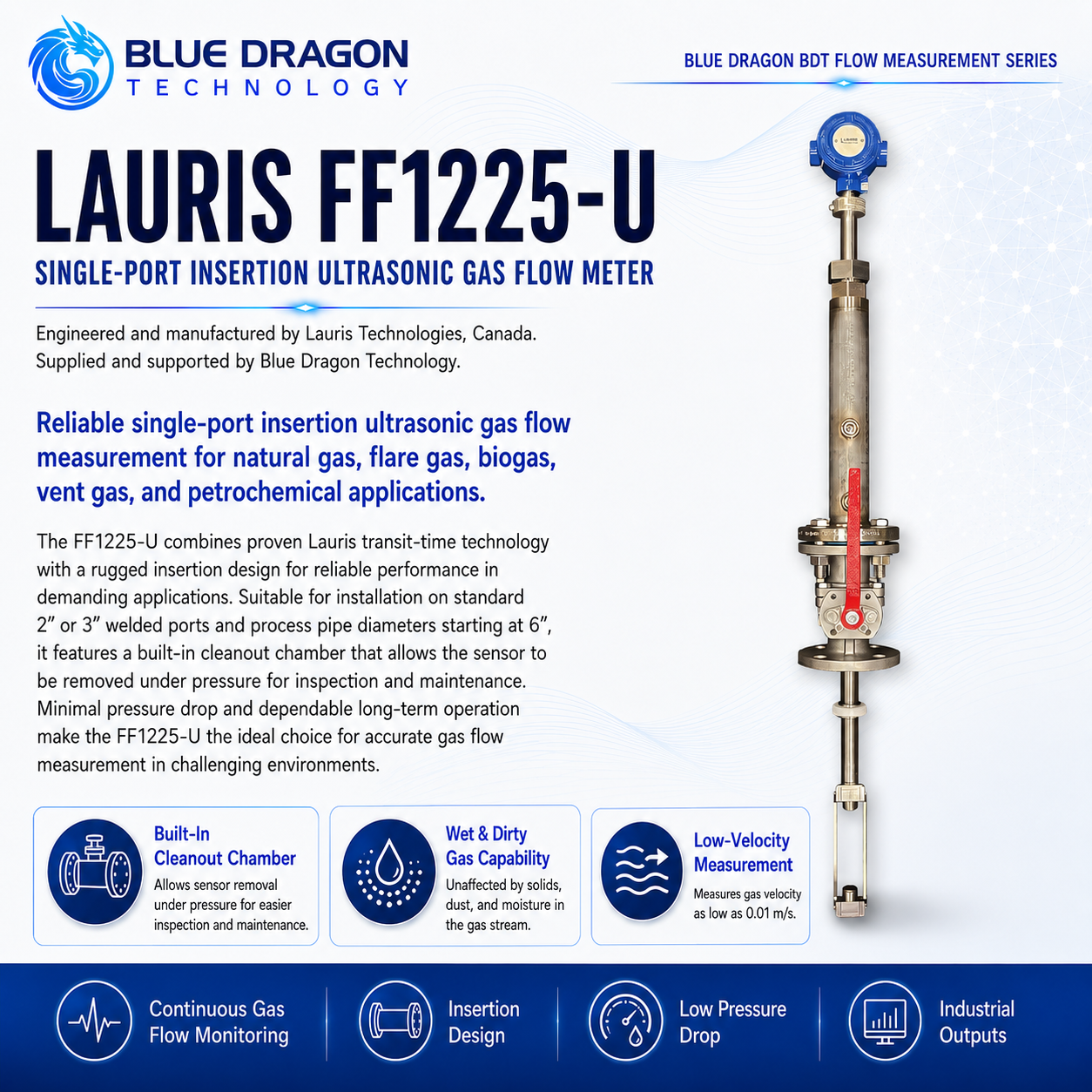
Lauris FF1225-U Single-Port Insertion Ultrasonic Gas Flow Meter

Single-port insertion ultrasonic gas-flow measurement for low-velocity flare, vent, wet and dirty gas retrofit applications.

Brand: Lauris Technologies Manufactured by: Lauris Technologies, Canada Supply & support: Blue Dragon Technology
Product Overview

Purpose-built measurement, clearly presented.

The Lauris FF1225-U is an insertion ultrasonic gas flow meter developed for low-velocity flare gas, vent gas and process-gas applications. It is particularly suited to retrofit projects replacing thermal mass, optical, Pitot, Annubar, target or other insertion meters whose performance is limited at low velocity or in wet and dirty gas.

The meter installs through a single process port in its FF1225-U configuration. A built-in cleanout chamber allows the sensor assembly to be removed under pressure for inspection and maintenance. Available configurations include different sensor materials, two- or three-inch process connections, local or remote electronics and hazardous-area approvals.

Distinctive Capabilities

  • Designed for replacement of conventional insertion meters
  • Minimum detectable gas velocity down to 0.01 m/s
  • Current cutsheet maximum gas velocity of 100 m/s
  • Measurement in wet, dirty and contaminated process gas
  • Operation under negative-pressure conditions
  • Two-inch or three-inch process-port options
Performance & Technical Data

The measurement method and the values that matter.

How it measures

Measurement Principle

The insertion assembly establishes an ultrasonic path through the flowing gas from one process-port location. Transit-time information from pulses travelling with and against the flow is processed to calculate gas velocity and volumetric flow. The ultrasonic technique does not depend on heat transfer from a heated sensor and is therefore less sensitive than thermal technologies to changes in gas composition, moisture, deposits and low gas velocity.

Repeatability0.2%
Process Temperature-40°C to +200°C
Meter typeSingle-port insertion ultrasonic gas flow meter
Operating principleUltrasonic transit-time measurement
Base designSingle path through one process port
Alternative configurationDual-path arrangement using two ports is available through Lauris configuration system

Complete Technical Data

Sensor materials
SS316, Monel or titanium; other materials available on request
Process connection
ANSI Class 150 raised-face flange, 2 in or 3 in
Velocity range
0.01 to 100 m/s
Published accuracy
1.0% to 2.5%; final performance is application dependent
Cleanout ports
1/2 in NPT
Pipe diameter
6 to 48 in
Process pressure
-0.5 to 19 barg
Ambient temperature
-45°C to +60°C
Power Supply
24 VDC or 100 to 250 VAC
Power consumption
2.5 W maximum
Communications & Outputs
4–20 mA, Modbus and HART
LCD display
Standard; may be omitted for low-temperature operation
Transmitter enclosure
Die-cast aluminum or stainless steel
Hazardous-area approvals
CSA or UL Class I, Division 1, Groups B, C and D, T4; ATEX Zone 1; IECEx Zone 1, subject to ordered configuration
Sunshade
GRP or stainless-steel sunshade available
Maintenance arrangement
Built-in cleanout chamber and sensor removal under pressure
Availability
Available for application review and quotation
Development noticePublished limits and approvals are configuration dependent. Retrofit suitability, insertion geometry and service clearance must be confirmed.
Industrial Use

Applications and industries.

Typical Applications

Flare-gas flow measurementStorage-tank vent gasVapor-recovery and tank-breathing systemsLow-velocity process-gas measurementBiogas and renewable-gas measurementWet and dirty gas streamsRetrofit of thermal mass flow metersRetrofit of Pitot, Annubar, target or optical metersNatural-gas and associated-gas measurementPower-generation fuel or process gasLarge-pipe insertion flow measurement

Industries Served

Biogas & Renewable GasChemical ProcessingFlare, Vent & Associated GasNatural Gas & LNGOil & Gas ProductionPetrochemicalPipelines & MidstreamPower GenerationRefineriesStorage Tanks & Vapor Recovery
Engineering & Integration

Built for specification, installation, and long-term operation.

Engineering determines the process-port geometry, insertion depth, sensor material, isolation and retraction arrangement, available clearance, pipe dimensions and flow-profile suitability required for a successful retrofit.

InstallationSingle insertion port
Current cutsheet velocity range0.01 to 100 m/s
Current cutsheet pipe range6 to 48 in
Service featureBuilt-in cleanout chamber and under-pressure removal

Meter Configuration

  • StandardFF1225-U single-path sensor assembly installed through one process port.
  • OptionalDual-path configuration using two process ports, subject to the selected Lauris model code.
  • StandardTwo-inch or three-inch ANSI Class 150 raised-face process connection.
  • Project EngineeredSensor material, insertion length, port location, isolation valve, cleanout arrangement, transmitter location and cable routing.
  • OptionalLocal or remote transmitter, stainless-steel enclosure, hazardous-area certifications and GRP or stainless-steel sunshade.
  • Project Engineeredsingle-path or optional dual-path arrangement; two- or three-inch ANSI Class 150 process connection; insertion length; SS316, Monel or titanium sensor material; isolation and retraction arrangement; local or remote transmitter; outputs; display; enclosure; sunshade; hazardous-area approvals.

Transducer & Pipe Interface

  • StandardDirect insertion into the process gas with no extracted sample or conditioning system.
  • Project EngineeredInsertion depth and sensor orientation are determined from the actual internal pipe diameter and port geometry.
  • Application DependentWet gas, liquid droplets, solids and deposits are tolerated, but the expected loading should be reviewed to define inspection and cleanout frequency.

Installation Geometry & Utilities

  • Project EngineeredConfirm whether an existing two-inch or three-inch port can be reused and whether its orientation, flange class, nozzle length and internal clearance are suitable.
  • Project EngineeredThe isolation valve, cleanout chamber and retraction mechanism must have sufficient clearance for safe sensor withdrawal.
  • Application DependentExisting insertion-meter ports may require modification because the ultrasonic sensor geometry differs from thermal, Pitot or target meters.
  • StandardSupply options are 24 VDC or 100 to 250 VAC.

Communications & Integration

  • Standard4–20 mA, Modbus and HART outputs are available.
  • Project EngineeredDefine flow engineering units, totalizer scaling, standard reference conditions, alarm values and communication mapping.
  • Application DependentExternal pressure and temperature measurements may be required when corrected or mass-flow information is needed.
  • OptionalThe LCD can be omitted where low-temperature operation or installation requirements make a local display unsuitable.

Verification & Calibration

  • Application DependentCalibration range and uncertainty requirements should match the actual minimum, normal and maximum gas velocities.
  • Project EngineeredRetrofit projects require confirmation of the actual internal pipe diameter, insertion depth, port geometry and configured flow area.
  • StandardCommissioning should verify sensor orientation, acoustic signal quality, zero-flow behavior, output scaling, totalizer operation and communication.
  • Application DependentEmissions or regulatory applications require a documented measurement and uncertainty basis appropriate to the reporting requirement.

Maintenance & Service

  • StandardUse the built-in cleanout chamber to remove accumulated deposits and inspect the sensor.
  • OptionalThe sensor assembly can be withdrawn under pressure using the supplied isolation and retraction arrangement.
  • StandardPeriodically inspect the sensor, process seals, isolation valve, cleanout ports, cable, transmitter enclosure and output stability.

Application Limits & Environmental Rating

  • Project EngineeredThe process flange, isolation valve, cleanout chamber and sensor assembly must be rated for the operating and design pressure and temperature.
  • Application DependentUnder-pressure withdrawal requires trained personnel, correct equipment and an approved isolation and maintenance procedure.
  • Application DependentFlare, vent and tank gases may be flammable, toxic, corrosive or oxygen deficient.
  • Project EngineeredHazardous-area certificates and electrical installation must match the supplied transmitter configuration and site classification.
Application Review

Application Engineering Notes

For retrofit projects, obtain drawings and photographs of the existing meter, process port, isolation valve, nozzle and available retraction clearance. Do not assume that an existing thermal or Pitot installation can accept the FF1225-U without modification.

Also obtain the pipe internal diameter, wall thickness, minimum and maximum flow, gas composition, pressure, temperature, moisture, liquid and solids loading, required accuracy, hazardous-area classification, output requirements and shutdown availability.

Application Engineering

Discuss your measurement application.

Share the sample, measurement range, operating conditions, project location, and timeline. Blue Dragon Technology will review the application and recommend the appropriate configuration.