Available Available for project-specific vertical insertion application review and quotation
Blue Dragon BDT Flow Measurement Series
FF1225-G

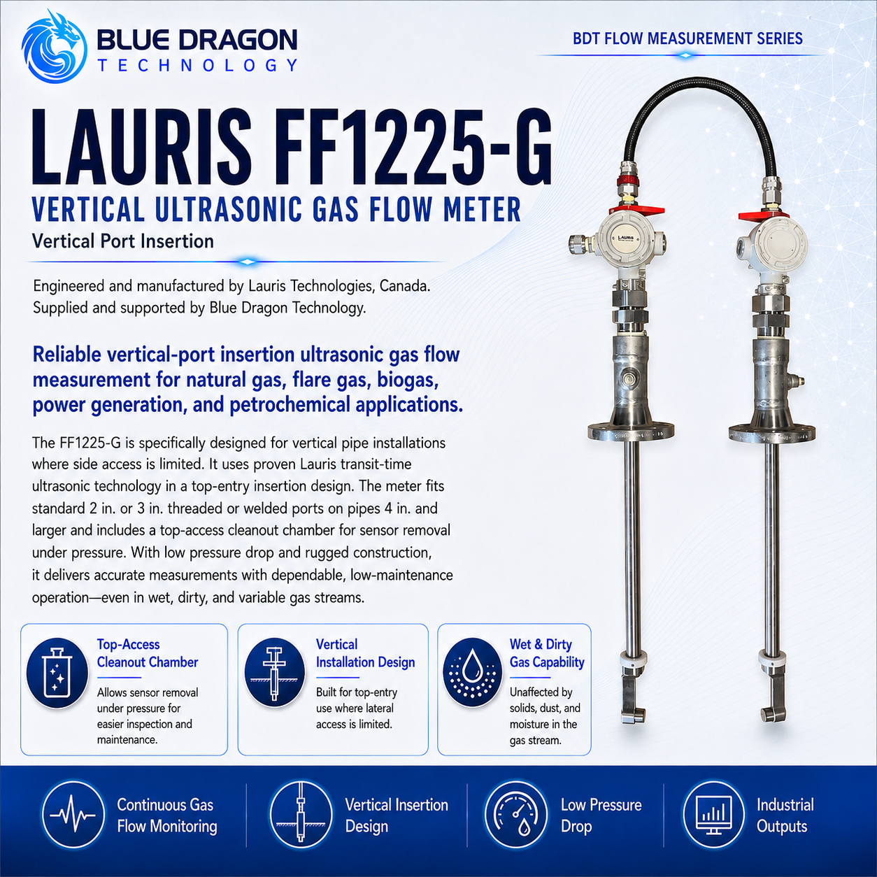
Lauris FF1225-G Vertical-Port Insertion Ultrasonic Gas Flow Meter

Vertical-port top-entry ultrasonic gas-flow measurement for pipes where side access is restricted.

Brand: Lauris Technologies Manufactured by: Lauris Technologies, Canada Supply & support: Blue Dragon Technology
Product Overview

Purpose-built measurement, clearly presented.

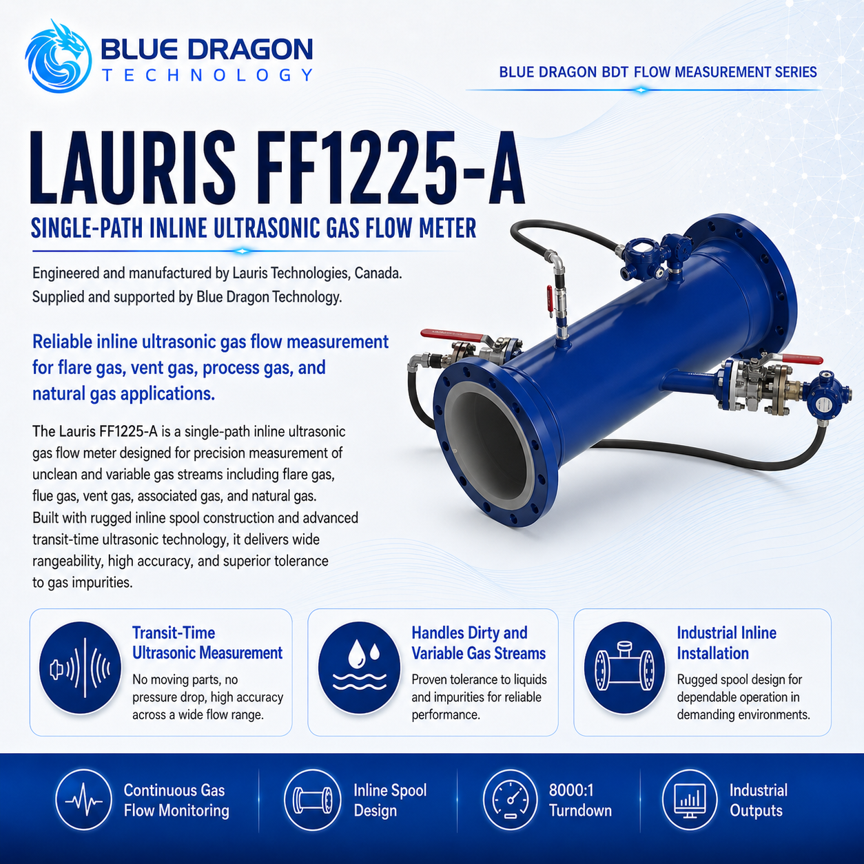
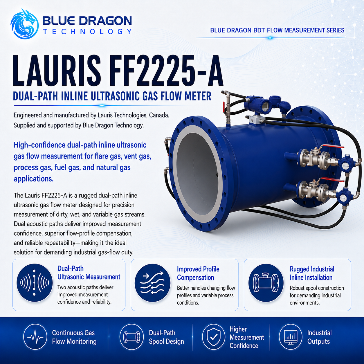
The Lauris FF1225-G is a vertical-port top-entry insertion ultrasonic gas flow meter for installations where side access is restricted. It applies Lauris transit-time measurement in a vertical arrangement and is available in single- or dual-path configurations.

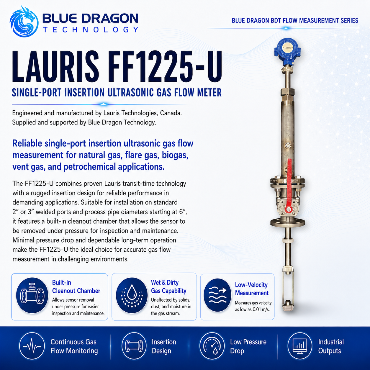
The design includes cleanout access and can be configured for sensor removal under pressure. It is suited to wet, dirty or contaminated gas streams, negative-pressure service and pipes from 4 to 50 inches.

Distinctive Capabilities

  • Suitable where side access is restricted
  • Minimum detectable gas velocity down to 0.01 m/s
  • Maximum gas velocity up to 100 m/s
  • Operation under negative-pressure conditions
  • Sensor removal under pressure subject to ordered configuration
  • Tolerance to dust, moisture and solids in the gas stream
Performance & Technical Data

The measurement method and the values that matter.

How it measures

Measurement Principle

The top-entry transducer arrangement transmits ultrasonic pulses with and against the flowing gas. The difference between the upstream and downstream transit times is processed to calculate gas velocity and volumetric flow. The top-entry arrangement provides the axial path required for low-velocity measurement while avoiding the lateral clearance needed by conventional side-mounted insertion designs.

Repeatability0.2%
Process Temperature-40°C to +200°C
Meter typeVertical top-entry insertion ultrasonic gas flow meter
Operating principleAxial ultrasonic transit-time measurement
Installation arrangementVertical-port top-entry insertion
Path configurationsSingle path (one port) or dual path (two ports)

Complete Technical Data

Velocity range
0.01 to 100 m/s
Published accuracy
1.0% to 2.5%; final performance is application dependent
Pipe diameter
4 to 50 in
Process pressure
-0.5 to 19 barg
Gas contamination
Designed for gas containing dust, moisture or solids
Maintenance arrangement
Built-in cleanout chamber and sensor removal under pressure available
Sensor materials
SS316, Monel or titanium; other materials available on request
Process connection
ANSI Class 150 raised-face flange, 2 in or 3 in
Cleanout ports
1/2 in NPT
Ambient temperature
-45°C to +60°C
Power Supply
24 VDC or 100 to 250 VAC
Power consumption
2.5 W maximum
Communications & Outputs
4–20 mA, Modbus and HART
LCD display
Standard; may be omitted for low-temperature operation
Transmitter enclosure
Die-cast aluminum or stainless steel
Hazardous-area approvals
CSA or UL Class I, Division 1, Groups B, C and D, T4; ATEX Zone 1; IECEx Zone 1, subject to ordered configuration
Sunshade
GRP or stainless-steel sunshade available
Availability
Available for project-specific application review and quotation
Development noticePipe range, pressure, temperature, path count, materials and approvals are configuration dependent. Final installation geometry must be reviewed during application review.
Industrial Use

Applications and industries.

Typical Applications

Flare-header gas-flow measurementVent-gas and relief-system monitoringLarge-diameter process-gas pipingVertical-access or restricted-clearance installationsNatural-gas and blended-gas flowAssociated-gas measurementWet and dirty gas streamsBiogas and renewable-gas measurementLarge-pipe retrofit projectsEnvironmental emissions monitoringAllocation or fiscal applications subject to selected path count and calibration

Industries Served

Biogas & Renewable GasChemical ProcessingFlare, Vent & Associated GasGas Metering & Custody TransferNatural Gas & LNGOil & Gas ProductionPetrochemicalPipelines & MidstreamPower GenerationRefineriesStorage Tanks & Vapor Recovery
Engineering & Integration

Built for specification, installation, and long-term operation.

Engineering focuses on the top-entry port locations, insertion geometry, acoustic path, isolation and retraction arrangement, pipe reinforcement, maintenance clearance and safe access required for the large-pipe installation.

InstallationVertical-port top-entry insertion
Current cutsheet velocity range0.01 to 100 m/s
Current cutsheet pipe range4 to 50 in
Service featureCleanout chamber and under-pressure sensor removal

Meter Configuration

  • StandardFF1225-G single-path vertical-port insertion configuration.
  • OptionalDual-path configuration using two ports, subject to the selected Lauris model code.
  • Project EngineeredProcess-port size, nozzle design, insertion depth, acoustic-path length, isolation valves, cleanout chamber, retraction mechanism and transducer material.
  • OptionalLocal or remote FF1225 transmitter, pressure and temperature inputs, alternative outputs and hazardous-area configurations.
  • Project Engineeredsingle- or dual-path configuration; two- or three-inch ANSI Class 150 process connection; insertion length; port and nozzle geometry; SS316, Monel or titanium sensor material; isolation and retraction arrangement; local or remote transmitter; outputs; display; enclosure; sunshade; hazardous-area approvals.

Transducer & Pipe Interface

  • StandardDirect measurement in the process pipe with no extracted sample or conditioning system.
  • Project EngineeredThe transducer assemblies penetrate the pipe through top-mounted process ports and are positioned to establish the required acoustic path.
  • Application DependentPipe diameter, wall thickness, internal condition, deposits, liquid accumulation, pressure, temperature and expected flow profile must be evaluated.

Installation Geometry & Utilities

  • Project EngineeredConfirm top access, overhead clearance, platform access, nozzle spacing, orientation, pipe reinforcement and structural loading.
  • Project EngineeredIsolation valves and the sensor-retraction system must be designed for the process pressure and available vertical clearance.
  • Application DependentThe pipe may require hot-tap planning, shutdown installation, welding procedures, reinforcement calculations and non-destructive examination.
  • StandardTransmitter power and communication requirements are selected from the FF1225 electronics platform.

Communications & Integration

  • Application DependentStandard and optional FF1225 analogue, pulse, HART and Modbus outputs can be selected for the project.
  • Project EngineeredPressure and temperature compensation, standard-flow conditions, totalizer scaling, alarms and DCS or SCADA mapping must be defined.
  • OptionalAdditional acoustic paths may provide enhanced accuracy or diagnostic information where required.

Verification & Calibration

  • Project EngineeredCalibration and uncertainty requirements must reflect the selected path count, pipe diameter, gas conditions and intended reporting function.
  • StandardDimensional inspection should verify nozzle spacing, insertion depth, acoustic-path geometry and the configured internal pipe diameter.
  • StandardCommissioning should verify sensor alignment, signal quality, zero-flow behavior, pressure and temperature inputs, outputs and totalizer configuration.
  • Application DependentLarge-diameter flare or emissions applications may require a documented flow-profile and uncertainty assessment.

Maintenance & Service

  • StandardUse the cleanout chamber to inspect contamination and remove deposits as required.
  • OptionalSensors can be withdrawn under pressure when the approved isolation and retraction arrangement is supplied.
  • StandardInspect valves, seals, transducer surfaces, cables, transmitter diagnostics and mechanical alignment.
  • Application DependentWet or dirty flare gas may require more frequent inspection than clean natural-gas service.

Application Limits & Environmental Rating

  • Project EngineeredTop-entry process ports, reinforcement, valves and retraction equipment must be rated for the design pressure and temperature.
  • Application DependentUnder-pressure sensor removal requires trained personnel, the correct retraction equipment, approved isolation procedures and sufficient vertical clearance.
  • Application DependentFlare headers may contain toxic, flammable, corrosive or oxygen-deficient gases and require appropriate operating procedures.
  • Project EngineeredHazardous-area certification, materials and electrical installation must match the actual site requirements.
Application Review

Application Engineering Notes

Provide the pipe outside diameter, wall thickness, schedule, internal diameter, material, elevation, orientation and available top-access clearance. Include photographs or drawings showing platforms, nearby piping and structures.

Also provide the minimum, normal and maximum flow, gas composition, pressure, temperature, moisture, liquid and solids loading, required accuracy, installation method, shutdown availability, hot-tap restrictions, hazardous-area classification and maintenance-access requirements.

Final meter configuration, materials, installation arrangement, performance, and certification are confirmed through application review.

Application Engineering

Discuss your measurement application.

Share the sample, measurement range, operating conditions, project location, and timeline. Blue Dragon Technology will review the application and recommend the appropriate configuration.