Available Available for application review, project configuration and quotation through Blue Dragon Technology
Blue Dragon BDT Flow Measurement Series
FF2225-A

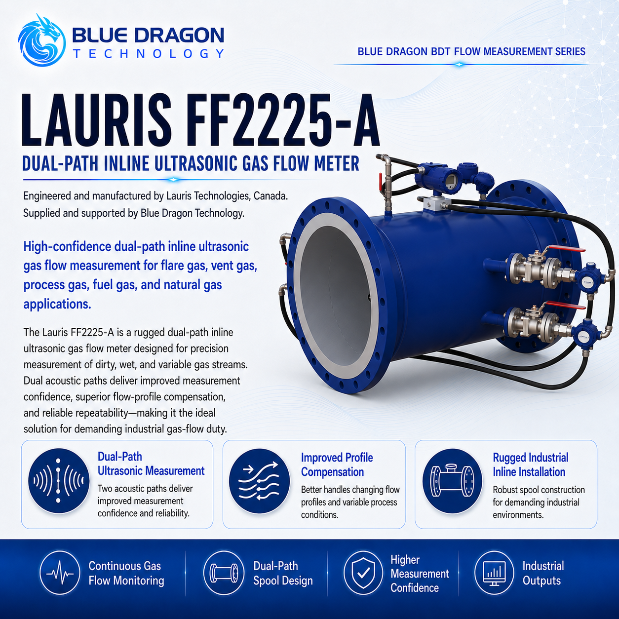
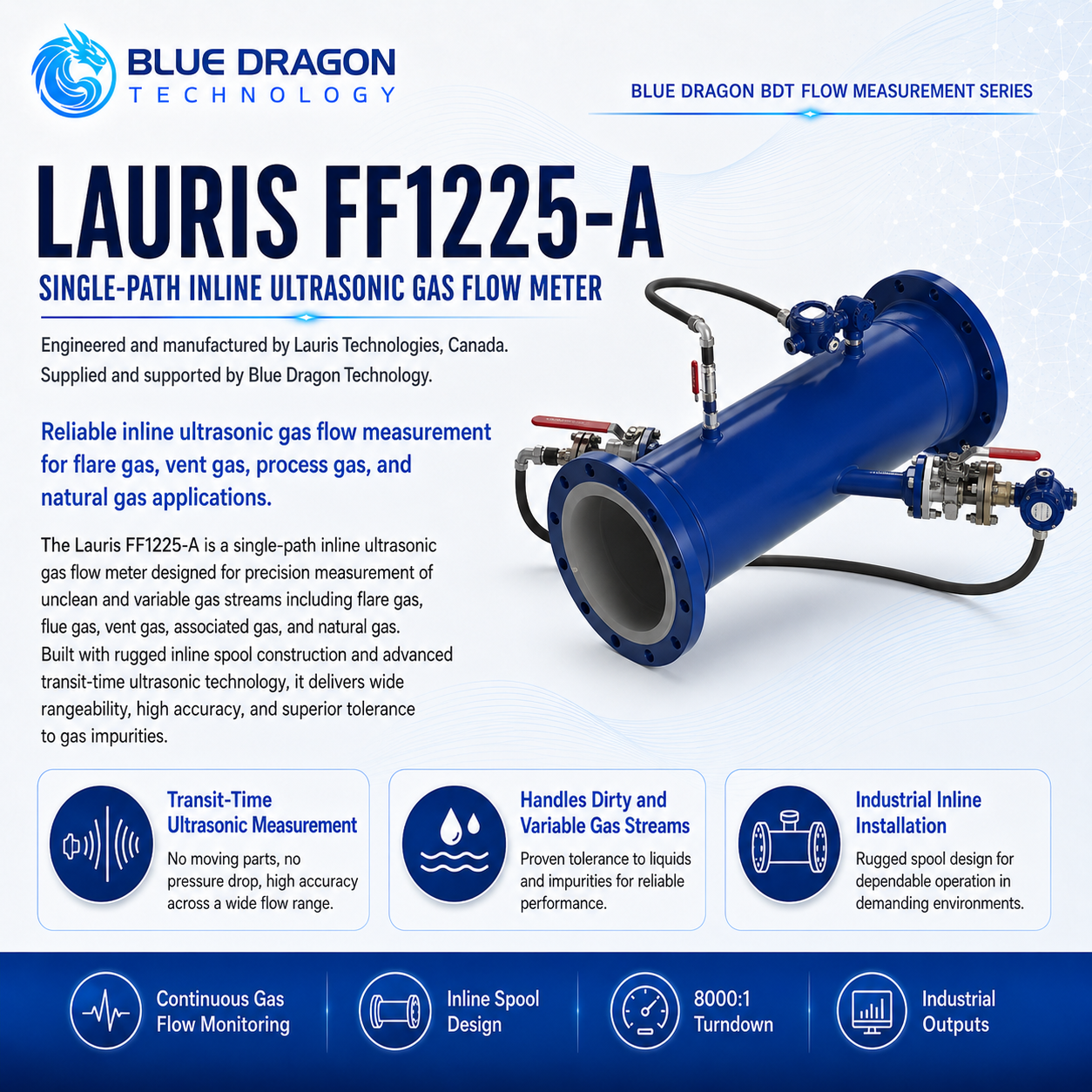
Lauris FF2225-A Dual-Path Inline Ultrasonic Gas Flow Meter

Dual-path axial ultrasonic gas-flow measurement for enhanced accuracy, path comparison and measurement confidence across demanding gas applications.

Brand: Lauris Technologies Manufactured by: Lauris Technologies, Canada Supply & support: Blue Dragon Technology
Product Overview

Purpose-built measurement, clearly presented.

The Lauris FF2225-A is a dual-path inline ultrasonic gas flow meter designed for applications requiring greater accuracy and measurement confidence than a basic single-path meter. Two independent axial acoustic paths provide additional flow information and allow the performance of the paths to be compared.

The FF2225-A is suitable for flare gas, vent gas, natural gas, blended gas, associated gas and other industrial gas streams. Meter-body materials, transducer metallurgy, pressure class, electronics, process connections, compensation inputs, hazardous-area approvals and calibration are selected for the project.

Distinctive Capabilities

  • Dual independent axial ultrasonic measurement paths
  • Path-to-path comparison for additional measurement confidence
  • Minimum detectable gas velocity down to 0.01 m/s
  • Measurement of wet, dirty and variable-composition gas
  • No moving measurement components
  • Very low permanent pressure loss
Performance & Technical Data

The measurement method and the values that matter.

How it measures

Measurement Principle

Two independent pairs of ultrasonic transducers transmit acoustic pulses with and against the direction of gas flow. The transmitter determines gas velocity from the upstream and downstream transit-time differences measured by each acoustic path. The two paths provide additional spatial averaging and allow the path results to be compared. This can improve measurement confidence where the flow profile, available straight pipe or required uncertainty makes a single-path arrangement insufficient.
Repeatability0.1%
Process Temperature-190°C to +250°C
Meter typeWetted, non-intrusive inline ultrasonic gas flow meter
Operating principleDual-path axial ultrasonic transit-time measurement
Acoustic pathsTwo paths with four transducers
Velocity range0.01 to 150 m/s

Complete Technical Data

Published dual-path accuracy
Within ±0.5% under suitable conditions; final uncertainty is application and calibration dependent
Higher multipath accuracy
Lauris publishes performance down to ±0.25% for appropriate higher-path designs
Turndown ratio
8,000:1
Pipe diameter
0.04 to 5 m (1.5 to 200 in)
Recommended straight run
10 pipe diameters upstream and 5 pipe diameters downstream
Process pressure
0.1 to 400 bar absolute
Liquid carryover
Current Lauris cutsheet states that the presence of liquids does not affect flow measurement; actual liquid loading must be reviewed
Gas-density capability
Published from 0.05 kg/m³; suitable for low-density gases including hydrogen
Transducer materials
SS316, SS316L, titanium, Hastelloy or Monel
Transducer cable length
Up to 30 m
Process connection
NPT or flanged transducer connections
Transducer servicing
Online-retractable arrangement available for removal under pressure
Measured and calculated parameters
Standard flow, actual flow, flow rate, totalized flow, molar mass, pressure and temperature
Power Supply
24 VDC nominal, 20 to 32 VDC; 120 or 220 VAC optional
Power consumption
2.5 W maximum
Analogue inputs
Two 4–20 mA inputs for pressure and temperature
Standard outputs
Modbus, frequency or pulse, one 4–20 mA output and HART
Optional analogue outputs
Up to twelve 4–20 mA outputs
Transmitter enclosure
Die-cast aluminum or stainless steel
Ingress protection
NEMA 4X and IP67
Hazardous-area approvals
CSA or UL Class I, Division 1, Groups B, C and D, T4; ATEX Zone 1; IECEx Zone 1, subject to ordered configuration
Sunshade
GRP or stainless-steel sunshade available
Availability
Available for application review and quotation
Development noticePublished accuracy and rangeability depend on the selected meter geometry, installation, calibration and process conditions. Final performance and certification are confirmed during application review.
Industrial Use

Applications and industries.

Typical Applications

Flare-gas and vent-gas measurementNatural-gas transmission and meteringBlended and variable-composition gasAssociated-gas measurementProcess-gas and fuel-gas measurementHydrogen and low-density gas measurementBiogas and renewable-gas measurementEnvironmental emissions reportingAllocation measurementFiscal or custody-transfer applications subject to calibration and approved configurationInstallations requiring greater accuracy than a single-path meter

Industries Served

Biogas & Renewable GasChemical ProcessingFlare, Vent & Associated GasGas Metering & Custody TransferHydrogen & SyngasNatural Gas & LNGOil & Gas ProductionPetrochemicalPipelines & MidstreamPower GenerationRefineries
Engineering & Integration

Built for specification, installation, and long-term operation.

Engineering determines whether the dual-path architecture provides the required uncertainty, flow-profile tolerance and diagnostic confidence, and defines the meter body, transducers, pressure class, electronics, compensation signals and calibration package.

Meter architectureDual-path inline axial ultrasonic meter
Published dual-path accuracyWithin ±0.5% under suitable conditions
Process interfaceComplete flow spool or engineered transducer installation
Primary selection basisRequired uncertainty, pipe geometry and process conditions

Meter Configuration

  • OptionalLocal integral transmitter or remote transmitter with up to 30 m of transducer cable.
  • Project EngineeredMeter-body material, pipe schedule, flange rating, flange face, transducer-port design, isolation arrangement and transducer metallurgy.
  • OptionalExternal pressure and temperature transmitters, multiple analogue outputs, stainless-steel transmitter enclosure and GRP or stainless-steel sunshade.
  • Application DependentHigher-path FF3225-A or FF4225-A configurations may be considered where the required uncertainty or flow-profile conditions exceed the FF2225-A capability.
  • Project Engineeredmeter-body diameter and length; pipe schedule; flange standard and pressure class; spool and transducer materials; two-path geometry; local or remote transmitter; cable length; retractable transducers; pressure and temperature inputs; analogue, pulse, HART and Modbus outputs; enclosure material; sunshade; hazardous-area approvals; calibration and documentation package.

Transducer & Pipe Interface

  • StandardDirect in-line gas measurement without an extracted sample or sample-conditioning system.
  • Project EngineeredThe two acoustic paths are positioned and sized according to the pipe diameter, flow profile and required measurement performance.
  • Application DependentGas composition, acoustic attenuation, liquid loading, solids, pressure, temperature and expected velocity distribution must be evaluated.

Installation Geometry & Utilities

  • StandardThe baseline installation recommendation is 10 pipe diameters upstream and 5 pipe diameters downstream.
  • Project EngineeredUpstream disturbances, elbows, valves, headers, reducers, flare-tip geometry and limited straight-run conditions must be reviewed when positioning the dual acoustic paths.
  • OptionalOnline-retractable transducers may be supplied with isolation valves and retraction equipment.
  • StandardNominal transmitter power is 24 VDC; AC-powered configurations are optional.

Communications & Integration

  • StandardModbus, frequency or pulse, one 4–20 mA output and HART are available.
  • Project EngineeredThe control-system interface should define standard-flow conditions, pulse scaling, totalizer behavior, Modbus registers, path diagnostics, alarms and handling of pressure or temperature input failure.

Verification & Calibration

  • Project EngineeredDefine the required calibration range, calibration medium, uncertainty target, certificate format and applicable metering standard.
  • Application DependentAllocation, fiscal and custody-transfer applications require a complete uncertainty assessment rather than relying only on the published meter accuracy.
  • StandardQuality records should preserve transducer pairing, acoustic-path dimensions, meter-body dimensions, material records, transmitter configuration and path identification.
  • StandardCommissioning should verify agreement between the two paths, configured pipe dimensions, compensation inputs, output scaling, totalizer operation and communication mapping.

Maintenance & Service

  • StandardPeriodically compare the two acoustic paths for changes in signal strength, transit behavior or calculated velocity.
  • StandardInspect transducers, process seals, cables, terminal connections, transmitter enclosure and diagnostic records.
  • OptionalRetractable transducers support inspection or replacement under pressure when the approved isolation system is included.
  • Application DependentPath disagreement may indicate contamination, liquid accumulation, flow-profile change, transducer deterioration or an incorrect process input and should be investigated.

Application Limits & Environmental Rating

  • Project EngineeredAll pressure-containing components must comply with the specified piping class, design pressure, design temperature and material requirements.
  • Application DependentHazardous-area certificates must match the supplied transmitter and electrical configuration.
  • Application DependentUnder-pressure servicing requires isolation valves, retraction equipment, approved procedures and trained personnel.
  • Project EngineeredSour gas, hydrogen, corrosive gas, cryogenic gas and high-pressure gas require application-specific materials and compatibility review.
Application Review

Application Engineering Notes

Specify the required measurement uncertainty and intended use clearly. A process-monitoring application, emissions-reporting system, allocation meter and fiscal or custody-transfer meter may require different calibration, documentation and installation controls.

Provide pipe drawings and details of upstream disturbances. Although the dual-path design offers greater spatial information than a single-path meter, the final performance still depends on flow profile, pipe dimensions, installation geometry, pressure and temperature inputs and calibration.

Application Engineering

Discuss your measurement application.

Share the sample, measurement range, operating conditions, project location, and timeline. Blue Dragon Technology will review the application and recommend the appropriate configuration.